Generating unit multi-synchronizing point automatic grid connection system

A technology for generator sets and power grid systems, which is applied in the direction of single-network parallel feed arrangement, etc., can solve problems such as single connection mode, inflexible grid-connection use, delay of unit grid-connection time, etc., so as to improve grid-connection efficiency and branch circuit The effect of choosing convenience and flexibility and improving the economic benefits of enterprises

Pending Publication Date: 2018-04-06
国投钦州发电有限公司
View PDF0 Cites 3 Cited by
  • Summary
  • Abstract
  • Description
  • Claims
  • Application Information

AI Technical Summary

Problems solved by technology

This not only delays the grid connection time of the unit, makes the operation of power supply and distribution on the system side unstable, and reduces the economic benefits of

Method used


Image

  • Generating unit multi-synchronizing point automatic grid connection system
  • Generating unit multi-synchronizing point automatic grid connection system
  • Generating unit multi-synchronizing point automatic grid connection system

Examples


Embodiment 1

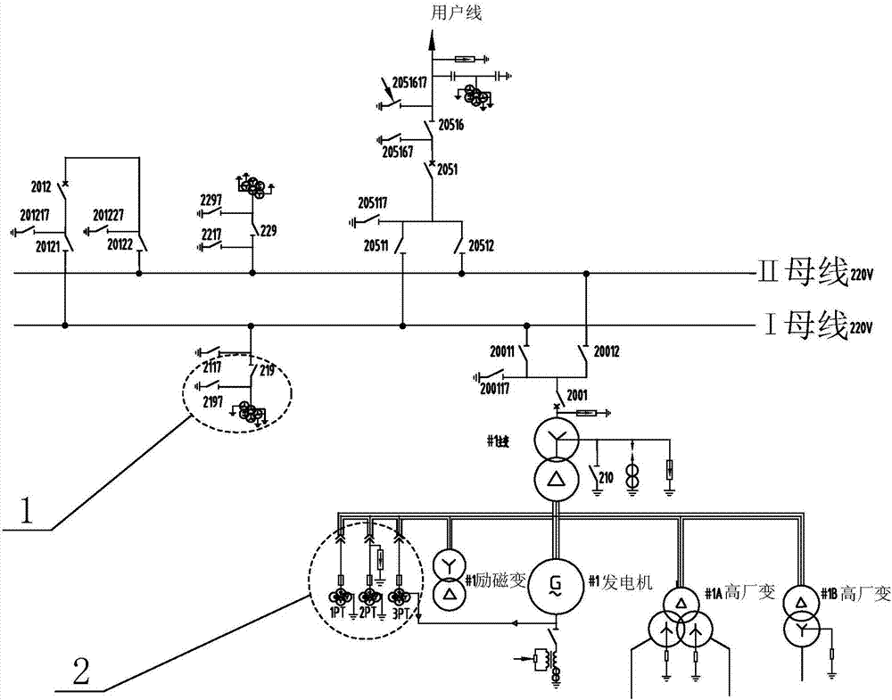
[0018] The multi-synchronization point automatic grid connection system of generator sets includes a grid system for generators to be connected to the grid synchronously and a synchronization device for controlling the automatic grid connection of the grid system. The structure on the main body of the synchronizing device is the same as that of the synchronizing grid connection device used in the prior art. The difference is: the improved grid-connected control unit 8 makes adaptive addition and connection of each electrical detection element and control knife switch, and makes suitable logic control instruction improvement in the controller on the synchronization device. The power grid system includes I busbars and II busbars connected in parallel, and n subscriber lines connected to the I busbars and the II busbars.

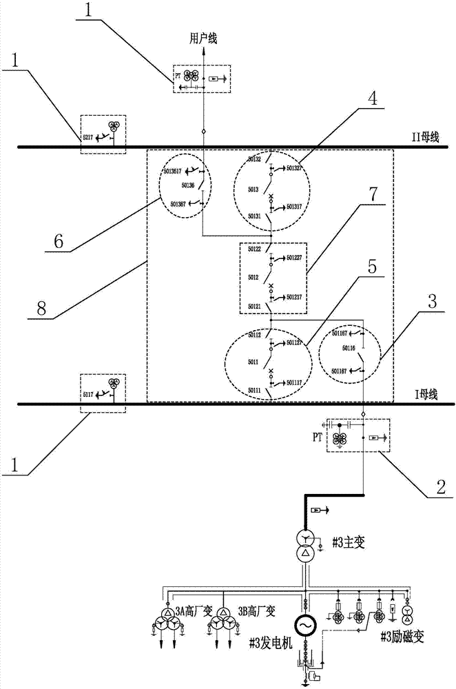
[0019] The power grid system further includes a grid connection control unit 8 corresponding to the number of subscriber lines. like figure 2 As shown, it i...

Embodiment 2

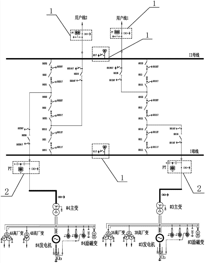
[0026] like image 3 As shown, the difference between the multi-synchronization point automatic grid connection system of the generator set and the first embodiment is that the value of n is 2. That is to say, two user lines are connected to I bus and II bus, and there are two generators for synchronous grid connection. There are 3 synchronization points on the synchronous grid connection system, which are in sequence on I bus, II bus and user line. Of course, according to the power supply and distribution requirements of the power grid, there can be multiple user lines connected to the two busbars. Therefore, the number of synchronous points in the system side where they are connected to the grid during the same period also increases accordingly, which can further improve the efficiency of the grid connection during the same period. reliability.


PUM


Abstract

The invention discloses a generating unit multi-synchronizing point automatic grid connection system. A system side voltage measuring unit is installed in an I bus, an II bus, and respective user lines that are connected to the I bus and the II bus. When a generating unit is connected to a grid, a to-be-connected side voltage measuring unit on the generating unit and a random system side voltage measuring unit performs sensing. When conditions for synchronizing grid connection are met, a grid connection control unit is controlled in a synchronizing apparatus, such that the grid connection control unit successively opens respective grid connection disconnections/switches. Compared with prior art, as long as a random synchronizing point in a grid system is normal, the generators can work inparallel, which greatly increases the grid connection efficiency of the generating unit and ensures stable operation of system side power supply. According to the invention, 2 parallel switches are provided for executing grid connection, so that even one parallel switch of the system has faults, the grid connection of the generators are not affected, and grid connection is much easier and more flexible in terms of branch selection.

Description

technical field [0001] The invention relates to an automatic grid-connecting device for a generating set, in particular to a multi-synchronizing point automatic grid-connecting system for a generating set. Background technique [0002] In a power plant, the simultaneous grid connection is a major operation before the power plant generates electricity. It is necessary to coordinate and cooperate among various systems such as excitation, steam turbine, knife switch, and DCS control, and finally realize the stable integration of the generator into the power grid and the stable transmission of electric energy into the power grid. Improper operation may cause abnormal accidents such as system fluctuation and oscillation. In severe cases, it will cause major electrical accidents such as asynchronous grid connection of generators, generator damage, and grid jumping. The principle of synchronous grid connection of generators is: by collecting the voltage of the voltage transformer ...

Claims


Application Information

Patent Timeline
IPC IPC(8): H02J3/42
CPCH02J3/42
Inventor 马猛忠杨建栋周邦栋李锋张伯兴张旭黄凯孙希龙
Owner 国投钦州发电有限公司
Why Eureka
Try Eureka