a bridge device

A bridge and closing device technology, applied in the direction of bridges, bridge construction, bridge materials, etc., can solve the problems of uneven stone particles, cumbersome operation, complex structure, etc., and achieve the effect of improving the crushing effect.

Active Publication Date: 2019-02-15
ANHUI XIANGNENG ELECTRIC POWER TECH CO LTD
View PDF6 Cites 0 Cited by
  • Summary
  • Abstract
  • Description
  • Claims
  • Application Information

AI Technical Summary

Problems solved by technology

The hammer crusher currently used in the market smashes the stone through the high-speed revolving hammer head, the stone particles are uneven, the hammer crusher is noisy, dusty, poor in stability, and the structure is complex and the operation is cumbersome.

Method used


Image

  • a bridge device
  • a bridge device
  • a bridge device

Examples


Embodiment Construction

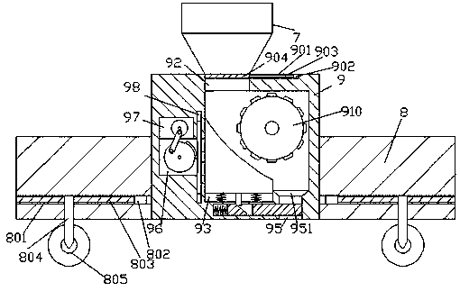
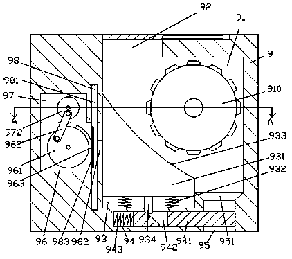
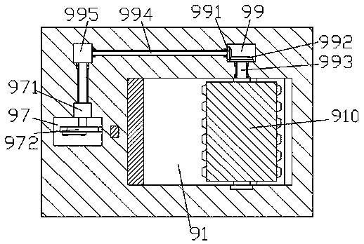
[0019] Such as Figure 1-Figure 5 As shown, a bridge device of the present invention includes a machine base 8 and a rock crusher 9 installed in the machine base 8, and a crushing part 91 is arranged in the rock crushing machine 9, and the crushing part 91 The inner top wall on the right side is provided with a stone inlet 92, and the top surface of the rock crusher 9 above the stone inlet 92 is connected and fixed with a conical bucket 7, and the left inner bottom wall of the fragmentation part 91 is A diversion chamber 93 is provided inside, and the inner bottom wall of the fragmented part 91 on the right side of the diversion chamber 93 is provided with a lower outlet 95 through which a conical groove is arranged on the top of the lower outlet 95. 951, the lifting and landing sliding block 931 extending upwards is connected with a sliding fit in the guide cavity 93, and the top extension section of the lifting and landing sliding block 931 extends into the crushing part 91 ...


PUM


Abstract

The invention discloses a bridge device. The bridge device comprises a machine base and a stone crushing machine arranged in the machine base; a fragmentation part is arranged in the stone crushing machine, a stone inlet is formed in the inner top wall of the right side of the fragmentation part, and a guide moving cavity is formed in the inner bottom wall of the left side of the fragmentation part; a lower discharge opening runs through the inner bottom wall of the fragmentation part on the right side of the guide moving cavity, and a conical groove is formed in the top of the lower dischargeopening; a lifting sliding block which extends upwards is connected with the interior of the guide moving cavity in a sliding and matched mode; the extension section of the top of the lifting slidingblock extends into the fragmentation part; the top, extending into the fragmentation part, of the lifting sliding block is provided with an arc-shaped surface extending to the right lower portion; afirst elastic element is arranged at the position, below the bottom of the lifting sliding block, in the guide moving cavity; a transmission groove is formed in the inner wall of the left side of thefragmentation part, a square groove is communicated with the interior of the inner top wall of the left side of the transmission groove, and a first guide moving groove extending up and down runs through the right side of the transmission groove. The bridge device is simple in structure and convenient to operate, improves the crushing effect of hardened fertilizer, reduces the manual workload, andimproves the stone crushing uniformity.

Description

technical field [0001] The invention relates to the field of bridges, in particular to a bridge device. Background technique [0002] High-performance concrete is a new type of high-tech concrete. It has good durability, homogeneity, stability and economy when applied to bridges. It has certain strength and high impermeability. It can greatly improve the performance of ordinary concrete. Based on modern concrete technology. Crushed stone is the most used raw material in high-performance concrete, and the thickness of crushed stone plays a key role in the performance of high-performance concrete. The hammer crusher currently used in the market smashes the stone through the high-speed revolving hammer head, the stone particles are uneven, the hammer crusher is noisy, dusty, poor in stability, and the structure is complex and the operation is cumbersome. . Contents of the invention [0003] The technical problem to be solved by the present invention is to provide a bridge ...

Claims


Application Information

Patent Timeline
Patent Type & Authority Patents(China)
IPC IPC(8): E01D21/00E01D101/24
CPCE01D21/00E01D2101/24
Inventor 莫金连汪任斌
Owner ANHUI XIANGNENG ELECTRIC POWER TECH CO LTD
Why Eureka
Try Eureka