Electric appliance placement rack

A technology for electrical equipment and placement racks, applied in the field of placement racks, can solve problems such as the inability to adjust the height of the bracket, the small placement area of ​​the equipment, and the inability to move at any time, so as to achieve firm and firm fixation, strengthen the effect of buffering and shock absorption, and increase the effect of friction

Inactive Publication Date: 2018-04-10
刘正南
View PDF5 Cites 3 Cited by
  • Summary
  • Abstract
  • Description
  • Claims
  • Application Information

AI Technical Summary

Problems solved by technology

[0003] However, there are some disadvantages in the current electrical equipment racks on the market. The height of the bracket cannot be adjusted, the shock absorption effect is poor, the equipment placement area is small, and at the same time, it cannot be moved at any time.

Method used


Image

  • Electric appliance placement rack
  • Electric appliance placement rack

Examples


Embodiment Construction

[0015] In order to make the technical means, creative features, goals and effects achieved by the present invention easy to understand, the present invention will be further described below in conjunction with specific embodiments.

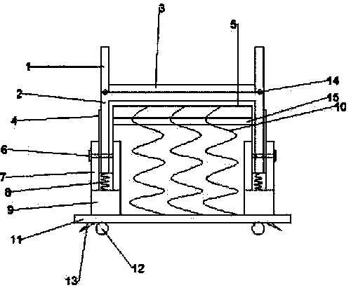
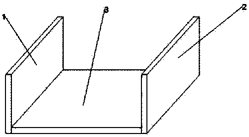
[0016] Such as Figure 1-2 As shown, an electrical equipment placement rack includes a movable baffle 1, a support frame body 2, a sleeve 7, a hydraulic cylinder 9, a backing plate 11 and a locking wheel device 13, and an elastic plate is fixedly installed on the upper part of the support frame body 2. 3. Movable baffles 1 are fixedly installed on both sides of the elastic plate, pin shafts 14 are fixedly installed on the bottom of the movable baffle 1, friction damping pads 5 are fixedly installed on the inner side of the support frame body 2, and the support frame body 2. A damping pad 4 is fixedly installed on the outside, a fixed plate 15 is fixedly installed inside the support frame body 2, a shock absorbing spring 10 is fixedly installed on ...


PUM


Abstract

The invention discloses an electric appliance placement rack. The electric appliance placement rack comprises movable baffle plates, a support body, sleeves, hydraulic cylinders, a cushion plate and wheel locking devices, wherein the movable baffle plates are fixedly arranged on two sides of an elastic plate; damping springs are fixedly arranged on the bottom of a friction damping cushion; the hydraulic cylinders are fixedly arranged on the bottoms of the sleeves; the multiple damping springs are arranged on the bottom of the friction damping cushion; the cushion plate is fixedly arranged on the bottoms of the hydraulic cylinders; and wheels are fixedly arranged on the bottom of the cushion plate. According to the electric appliance placement rack, a fixing plate is arranged and is fixedlyconnected with the support body, so that stability of the electric appliance placement rack is improved; the electric placement rack is provided with the movable baffle plates, the elastic plate, thefriction damping cushion, fixing bolts, the hydraulic cylinders, the damping springs and the wheels, so that the good buffering and damping effect of the electric appliance placement rack can be ensured; and the electric appliance placement rack is convenient to move, large in use area, and meanwhile very stable and firm, and thus has better use prospect.

Description

【Technical field】 [0001] The invention relates to a placement rack, in particular to an electrical equipment placement rack. 【Background technique】 [0002] There are many kinds of electrical equipment. When the electrical equipment is running, some of its parts and even itself can perform different forms of mechanical movement. It is difficult to avoid the support problem of the cantilever beam in the assembly process of large electrical equipment. In many cases, the assembly process of the workpiece requires a support that is not too heavy, quick to use, and easy to move as the support of the workpiece. At the same time, the curved surface of the workpiece of electrical equipment needs to be protected. However, the existing jack supports are difficult to meet the actual assembly requirements, often resulting in slow assembly speed, laborious work, low efficiency, poor quality and damage to workpieces. Current large electrical equipment needs to be placed on a support whe...

Claims


Application Information

Patent Timeline
Patent Type & Authority Applications(China)
IPC IPC(8): F16M3/00F16M7/00F16F15/023F16F15/04
CPCF16M3/00F16F15/023F16F15/046F16M7/00
Inventor 刘正南
Owner 刘正南
Why Eureka
Try Eureka