Lamp optical system for automobile

A technology for optical systems and lamps, applied in the field of optical systems, can solve the problems of occupying a large body space and achieve the effect of improving the utilization rate

Pending Publication Date: 2018-04-10
HASCO VISION TECHNOLOGY CO LTD
View PDF0 Cites 9 Cited by
  • Summary
  • Abstract
  • Description
  • Claims
  • Application Information

AI Technical Summary

Problems solved by technology

However, in the prior art, in order to realize different functions of vehicle lamps, different cavities are generally used to realize different functions. For example, light sources of different colors have different module structures to realize them. Although this method meets the needs of vehicle design and production The requirements of laws and regulations to be followed in the process, but under this design idea, each functional module will occupy a large amount of car body space, and in view of the current trend of flat car body space, the design idea of ​​the existing technology is in the application There have been obvious deficiencies

Method used


Image

  • Lamp optical system for automobile
  • Lamp optical system for automobile
  • Lamp optical system for automobile

Examples


Embodiment 1

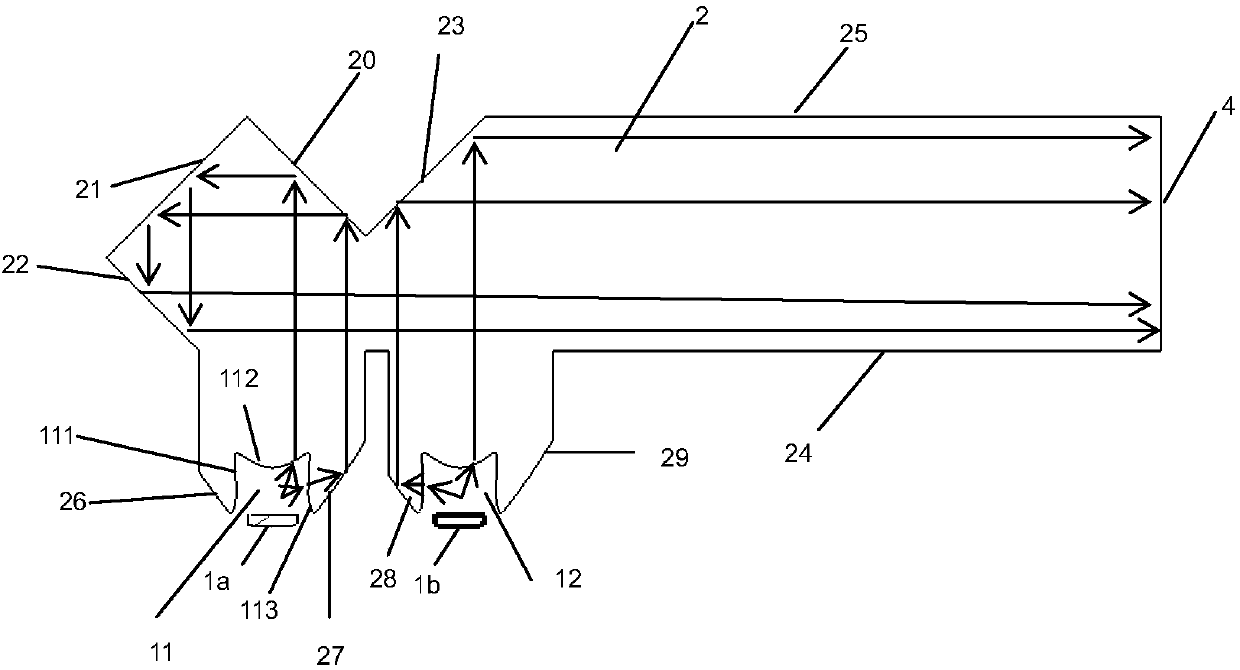
[0030] Such as Figure 1 to Figure 3 In the shown optical system of a vehicle lamp, the entire optical system of a lamp includes a light source 1 a , a light source 1 b and a thick-walled light guide 2 . The thick-walled light guide 2 is an integral polyhedron structure, and the inner wall of the polyhedron structure is mainly composed of an optical coupling surface 20, an optical coupling surface 21, an optical coupling surface 22, an optical coupling surface 23, an optical coupling surface 26, an optical coupling surface 27, an optical The coupling surface 28 , the optical coupling surface 29 , the bottom surface 24 , the top surface 25 and the light emitting surface 4 are composed.

[0031] Grooves 11 and 12 are opened on the thick-walled light guide 2, respectively corresponding to the light sources 1a and 1b. The light emitted from the light source 1a enters the thick-walled light guide 2 through the groove bottom 112 and groove walls (111 and 113) of the groove body 11,...

Embodiment 2

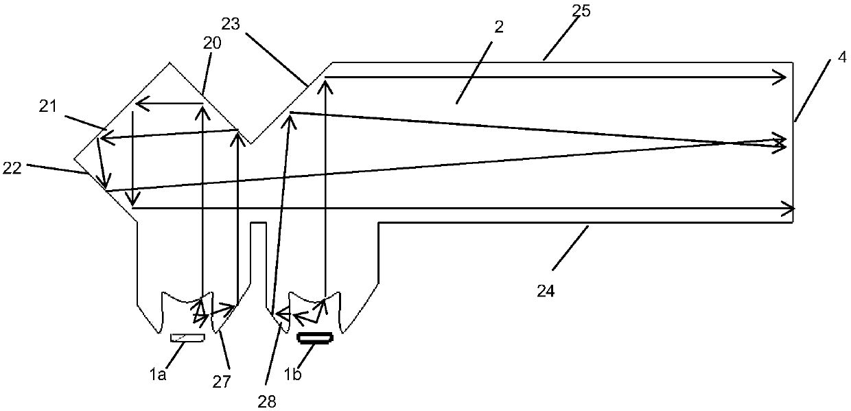
[0041] Such as Figure 4 Shown, is another embodiment of the present invention, with respect to the difference of embodiment 1, the plane of the optical coupling surface 23 in embodiment 1 is changed into the curved surface in the figure (with respect to the thick-walled light guide of polyhedron is inner convex surface ), that is, the optical coupling surface 23b in the figure.

[0042] Similarly, each optical coupling surface in Embodiment 1 can be a plane, an arc or a free-form surface

Embodiment 3

[0044] Such as Figure 5 As shown, it is another embodiment of the present invention. Compared with Embodiment 1, the difference is that the groove structure of the light-incoming regions of the two light sources is simplified as a convex surface protruding outward relative to the polyhedron, that is, in the figure The convex surfaces 51 and 52 are respectively used to receive the light emitted by the two light sources.


PUM


Abstract

The invention discloses a lamp optical system for an automobile. The lamp optical system for the automobile comprises two light sources, a polyhedral thick-wall light guide and two light inlet areas.The two light sources are homochromatic or non-homochromatic light sources. The two light inlet areas guide the light rays from the two light sources into the thick-wall light guide. The light rays from the two light sources enter from two outwards protruding surfaces of the polyhedron, are collimated and then are emitted from the same light outlet surface after being reflected by different optical coupling surfaces or a coupling surface set. Therefore, the space utilization rate of an automobile lamp is improved, and different functions of the automobile lamp are realized.

Description

technical field [0001] The invention relates to a novel optical system of a vehicle lamp capable of realizing various functions. Background technique [0002] Due to the obvious advantages of LED light sources such as fast response, low energy consumption, and stable chromaticity, there are more and more scenes where LED light sources are used in vehicle lamps. However, in the prior art, in order to realize different functions of vehicle lamps, different cavities are generally used to realize different functions. For example, light sources of different colors have different module structures to realize them. Although this method meets the needs of vehicle design and production The requirements of laws and regulations to be followed in the process, but under this design idea, each functional module will occupy a large amount of vehicle body space. There have been obvious deficiencies. Contents of the invention [0003] The technical problem to be solved by the present inv...

Claims


Application Information

Patent Timeline
IPC IPC(8): F21S41/00F21V7/22F21V15/01F21V8/00F21W102/00F21Y115/10
CPCF21V7/22F21V15/01F21Y2115/10B60Q2400/20F21S43/40F21S43/239F21S43/14
Inventor 胡尚斌张腾刘西原何士群胡晓翔
Owner HASCO VISION TECHNOLOGY CO LTD
Why Eureka
Try Eureka