
A coal mine blasthole plugging device

A plugging device and blasthole technology, applied in the field of mining equipment, can solve the problems of reducing blasting efficiency, easy plugging, and long operation time, and achieve the effects of reducing the risk of gas explosion, preventing flame spray, and having a simple structure

Active Publication Date: 2019-05-17
何洪彬
View PDF9 Cites 1 Cited by
  • Summary
  • Abstract
  • Description
  • Claims
  • Application Information

AI Technical Summary

Problems solved by technology

[0002] At present, when coal mining is carried out in the coal mine field, it is often necessary to use gunpowder to blast the ore body. After the ore body is drilled to a certain depth, the gunpowder is inserted into the blast hole. In order to improve the blasting quality and efficiency, the blast hole will be blocked. The blasting force is concentrated around the gunpowder, and the blasthole is usually drilled by a drilling rig. The inner wall of the blasthole is usually irregular in shape. The internal sloshing increases the hole wall, and the blasting effect is poor due to the leakage of the impact force. The traditional method of sealing the blast hole is to insert blasting mud into the blast hole. Because the blasting mud is paste-like and has a certain degree of plasticity, it is easy to seal it incorrectly. The impact force released from the depth of the blasthole spreads outward along the blasthole, and it is easy to push the blasting mud out, dispersing the blasting force, and a large amount of dust will be generated during the explosion process. The supply of blasting mud is inconvenient, and the filling process is numerous. The labor intensity of workers Large size, long working time, difficult to control the plugging quality, especially when there is water in the blast hole, it is easy to cause the phenomenon of explosive failure. The existing colloidal material blasting mud can reduce harmful gases and reduce dust. However, due to condensation and hardening Slow speed, high cost, high heat release and high cost during the condensation process, it is difficult to popularize and apply
Existing mud plugs for blocking blast holes are mainly divided into bottom cone mud plugs, wedge-shaped mud plugs and expansion screw mud plugs. Bottom cone mud plugs need to be used in conjunction with existing mud plugs to reduce blasting costs. s efficiency
However, a simple liquid or gas blockage can weaken the blasting peak and prolong the action time of the blasting gas. In the process of use, additional water bags need to be filled, which is time-consuming and laborious, and reduces the blasting efficiency.
[0003] Publication No. CN202255148U discloses a blasthole occluder, which includes a columnar plug body. The round surface of the cylindrical plug body is integrally formed with densely distributed barbs. The utility model adopts a structure in which the round surface of the cylindrical plug body is integrally formed and densely distributed. After entering the blasthole, the barb acts on the inner wall of the blasthole and deforms along the radial direction of the columnar plug body, generating a radially outward prestress. While expanding, the barb is used to clamp the surface of the blasthole wall, and multi-point contact increases friction , so it has a high blocking strength. Under the impact of blasting high-pressure gas, the barb has good self-locking performance. Usually, the inner wall of the blast hole is uneven, and it is difficult for the device to be evenly stressed when it is clamped. In some cases, there will be gaps in the plugging, and the plugging effect will not be good.

Method used


Image

  • A coal mine blasthole plugging device

Examples


Embodiment Construction

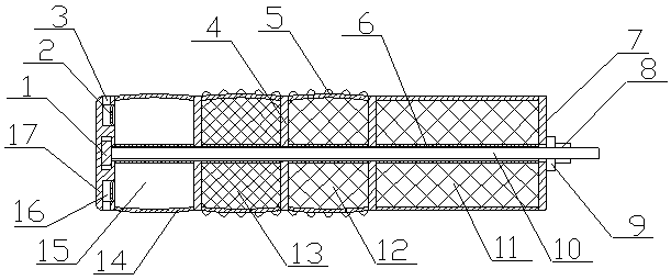
[0028]A coal mine blasthole plugging device of the present invention is realized in this way. When in use, when the blasthole is blocked, the present invention is first inserted into the blasthole, and when the bottom plate (7) is blasted toward the blasthole opening, it is then blasted out of the blasthole. Pull back the screw (10), the screw (10) drives the top plate (17) to move out of the blast hole, and then the elastic sleeve (14) is squeezed and swells, and the multiple rubber sleeves (6) on the screw (10) are respectively pressed Squeeze and compress, the clay in the clay chamber (11) deforms and bulges to seal the outermost side of the blasthole, and the gravel in the gravel chamber (12) deforms and swells under pressure to drive the outer friction protrusion (5) and the inner wall of the blasthole Closely fit, and then block the blast hole in the middle position, the water in the water storage chamber (13) is compressed and deformed to swell, driving the outer frictio...


PUM


Abstract

The invention discloses a coal mine blast hole plugging device. According to the coal mine blast hole plugging device, through matching of an elastic sleeve and a screw, a blast hole is plugged in a multistage mode, and the outer side of the elastic sleeve can be tightly attached to the hole wall of the blast hole. The outer side of the elastic sleeve can be tightly attached to the hole wall of the blast hole during plugging, plugging is tighter, and the plugging effect is improved effectively. The coal mine blast hole plugging device is characterized in that a top plate is arranged at one endof the elastic sleeve, is made of rigid materials and is provided with two liquid outlet grooves; plugging pieces are arranged in the liquid outlet grooves, are of an arc-shaped piece structure and are made of plastics; the outer side of the top plate is provided with two liquid outlet holes communicating with the two liquid outlet grooves correspondingly; the middle of the top plate is providedwith a round limiting groove; a bottom plate is arranged at the other end of the elastic sleeve and is made of rigid materials; the middle of the bottom plate is provided with a through hole; and a plurality of separation plates are arranged in the elastic sleeve to divide the inside of the elastic sleeve into a mixed liquid cavity, a water storage cavity, a gravel cavity and a clay cavity.

Description

technical field [0001] The invention relates to a coal mine blast hole sealing device, which relates to a device used in coal mines to block blast holes, and belongs to the field of mining equipment. In particular, it relates to a plugging device for multi-stage sealing of the blast hole through the cooperation of the elastic sleeve and the screw rod, and can make the outer side of the elastic sleeve closely fit the wall of the blast hole. Background technique [0002] At present, when coal mining is carried out in the coal mine field, it is often necessary to use gunpowder to blast the ore body. After the ore body is drilled to a certain depth, the gunpowder is inserted into the blast hole. In order to improve the blasting quality and efficiency, the blast hole will be blocked. The blasting force is concentrated around the gunpowder, and the blasthole is usually drilled by a drilling rig. The inner wall of the blasthole is usually irregular in shape. The internal sloshing ...

Claims


Application Information

Patent Timeline
Patent Type & Authority Patents(China)
IPC IPC(8): F42D1/18
CPCF42D1/18
Inventor 何洪彬
Owner 何洪彬
Learn More