
Temperature control device for sending mold

A temperature control device and mold technology, applied in temperature control, measuring device, optical radiation measurement, etc., can solve the problem that the temperature sensing element cannot truly reflect the actual temperature of the mold, and achieve accurate mold temperature, rapid heating, and accurate measurement Effect

Inactive Publication Date: 2018-04-10
MIRLE AUTOMATION CORPORATION
View PDF8 Cites 0 Cited by
  • Summary
  • Abstract
  • Description
  • Claims
  • Application Information

AI Technical Summary

Problems solved by technology

However, the temperature sensing element is set on the heat conduction plate instead of the mold, so the temperature sensed by the temperature sensing element cannot truly reflect the actual temperature of the mold

Method used


Image

  • Temperature control device for sending mold
  • Temperature control device for sending mold
  • Temperature control device for sending mold

Examples


Embodiment Construction

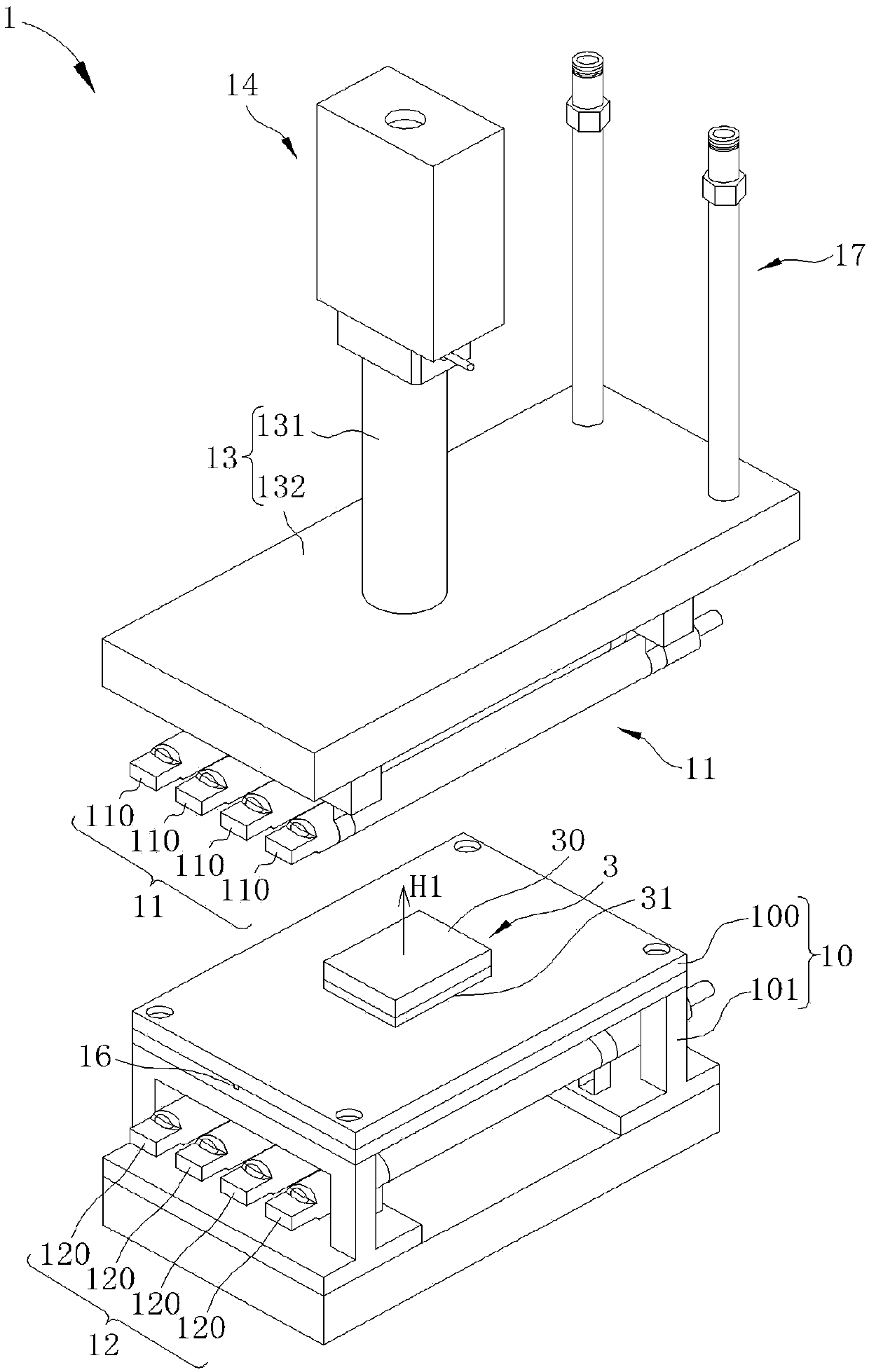
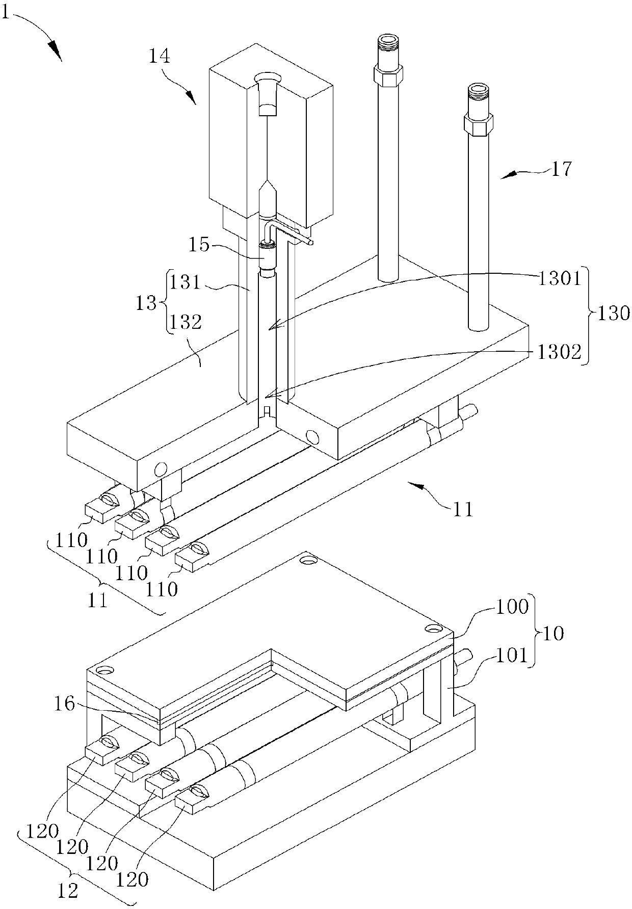
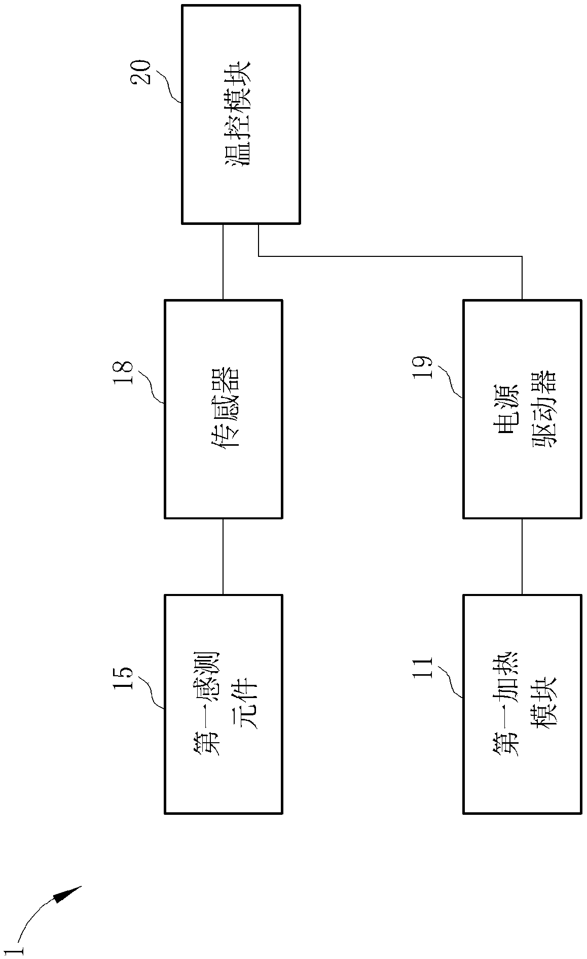
[0053] see Figure 1 to Figure 3 , figure 1 It is a schematic diagram of the appearance of the temperature control device 1 of the first embodiment of the present invention, figure 2 It is a partial sectional view of the temperature control device 1 according to the first embodiment of the present invention, image 3 It is a functional block diagram of the temperature control device 1 according to the first embodiment of the present invention. Such as Figure 1 to Figure 3 As shown, the temperature control device 1 includes a base 10, a first heating module 11, a second heating module 12, a fixing mechanism 13, an adjustment seat 14, a first sensing element 15, a second sensing element 16 . A cooling water circuit 17 , a sensor 18 , a power driver 19 and a temperature control module 20 .

[0054] The base 10 is used to support a mold 3, the first heating module 11 is arranged above the base 10 and spaced apart from the mold 3, the first heating module 11 heats an upper si...


PUM


Abstract

The invention discloses a temperature control device which contains a base, a first heating module, a fixing mechanism, a first sensing element and a temperature control module, the base is used for supporting a mold, and the first heating module is disposed above the base and spaced from the mold. The first heating module heats the mold in a non-contact manner, and the fixing mechanism is disposed above the base and fixes the first heating module, wherein a channel is formed in the fixing mechanism, a first sensing element is disposed in the channel, and the first heating module is located between the first sensing element and the base. When the first heating module heats the mold, the first sensing element senses a thermal radiation with a wavelength of thermal radiation emitted by the mold through the channel, and the temperature control module controls the temperature of the mold according to the thermal radiation.

Description

technical field [0001] The invention relates to a temperature control device for sensing and controlling the temperature of a mold, in particular to a temperature control device for sensing and controlling the temperature of a mold in a non-contact manner. Background technique [0002] The existing mold heating device uses a heat conducting plate and an electric heating tube to heat the mold, wherein the electric heating tube is embedded in the heat conducting plate, and the heat conducting plate directly contacts the mold when the electric heating tube is heating, so as to transfer the heat energy generated by the electric heating tube to the mold evenly. That is to say, the existing mold heating device indirectly heats the mold in a contact mode, but the mold is not directly heated during the heating process, so the heating rate is limited by the material characteristics (heat conduction number) of the heat conducting plate and there is no way to effectively improve. In a...

Claims


Application Information

Patent Timeline
Patent Type & Authority Applications(China)
IPC IPC(8): G05D23/20G01J5/00
CPCG05D23/20G01J5/00
Inventor 彭中晖邱明哲
Owner MIRLE AUTOMATION CORPORATION
Learn More