
Bait feeding device

A kind of equipment and bait technology, applied in the field of bait feeding equipment, can solve the problems of inability to feed, reduce the distance of bait, and small range of bait, and achieve the effect of expanding the range, improving efficiency, and evenly spreading bait

Inactive Publication Date: 2018-04-13
李毅宏
View PDF0 Cites 6 Cited by
  • Summary
  • Abstract
  • Description
  • Claims
  • Application Information

AI Technical Summary

Problems solved by technology

[0002] Marine fishery is one of the important contents of the marine industry, including mariculture and marine fishing and other activities. Marine fishery refers to the social production sector that catches and breeds fish and other aquatic animals and seaweeds and other aquatic plants to obtain aquatic products. It is generally divided into Marine fishery, freshwater fishery, fishery can provide food and industrial raw materials for people's life and national construction. In the process of marine fishery breeding, fishermen need to regularly feed the pond. The way of manual feeding is generally shore feeding or boat feeding. The side feeding method makes it easy for the bait to be washed to the shore by the current, resulting in a waste of bait. The way of feeding by boat is also due to the draft of the hull, so it is not possible to feed at shallower positions. The device can only feed in a single direction, and the feeding of the bait is not uniform enough. At the same time, the bait is easy to condense together after being damp. The existing feeding device for marine fishery cannot break up the bait before feeding, so that the bait is thrown The distance to go out is reduced, the range of bait delivery is small, and it is not conducive to fish foraging

Method used


Image

  • Bait feeding device
  • Bait feeding device
  • Bait feeding device

Examples


Embodiment Construction

[0015] The technical solutions in the embodiments of the present invention will be clearly and completely described below with reference to the accompanying drawings in the embodiments of the present invention. Obviously, the described embodiments are only a part of the embodiments of the present invention, but not all of the embodiments. Based on the embodiments of the present invention, all other embodiments obtained by those of ordinary skill in the art without creative efforts shall fall within the protection scope of the present invention.

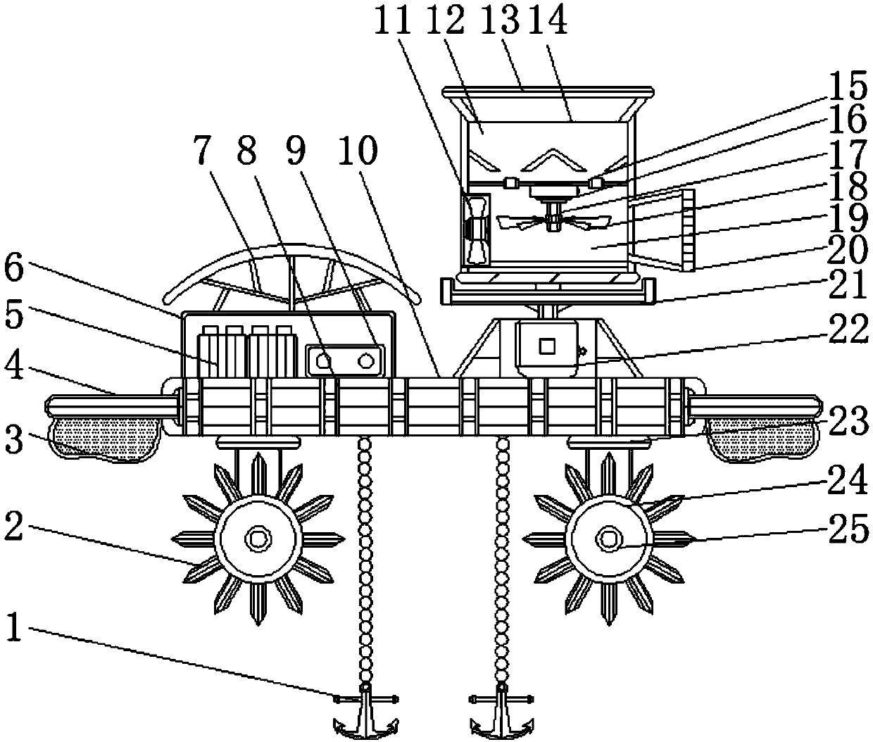
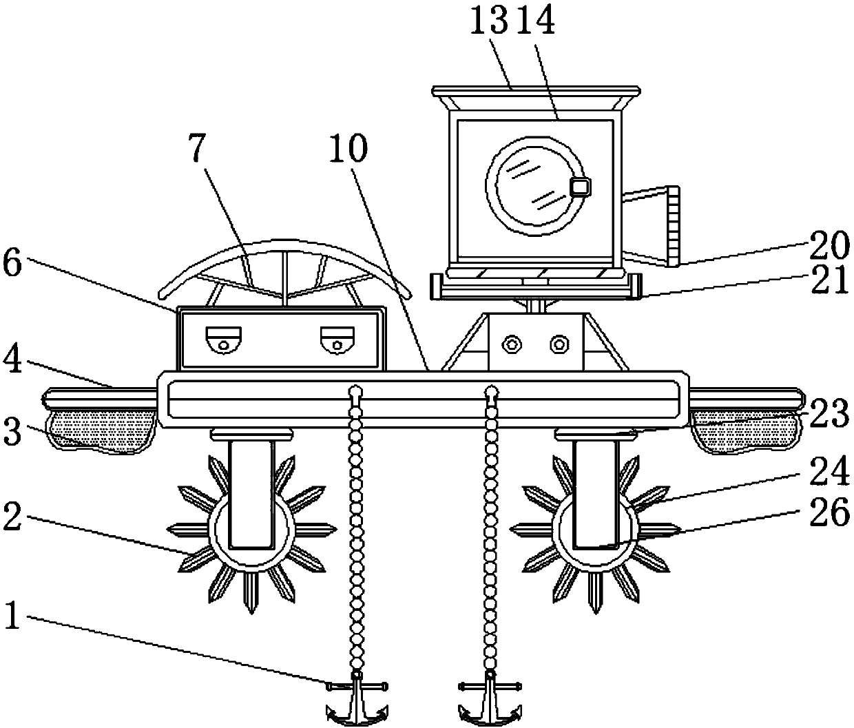
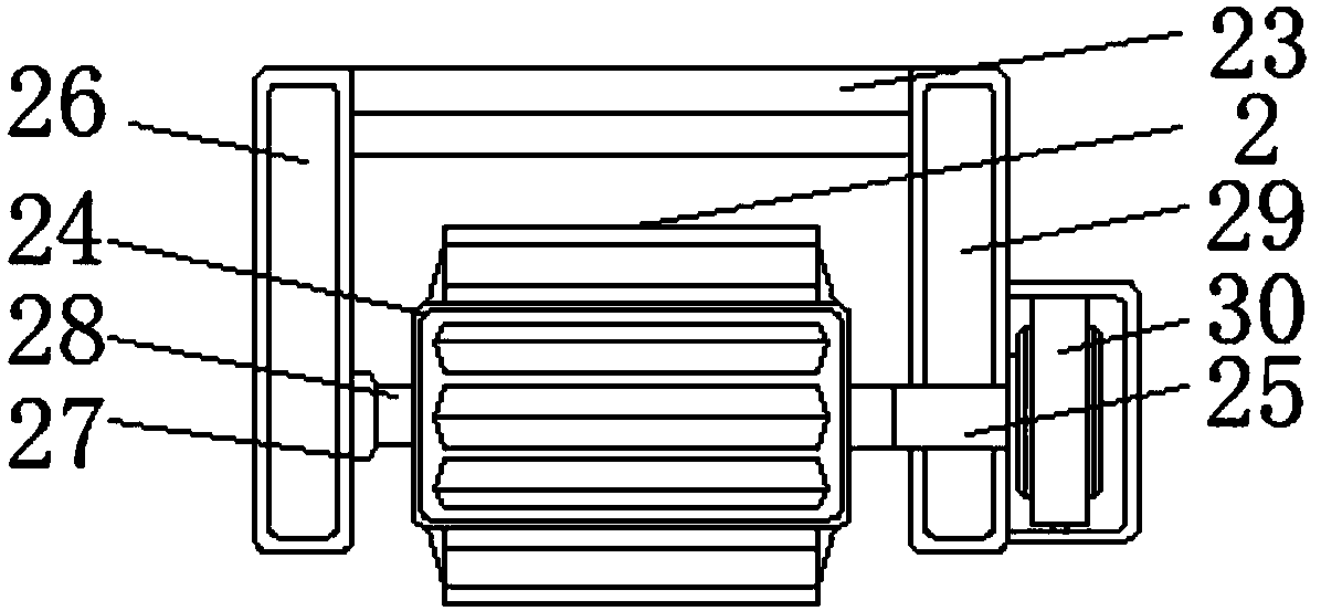
[0016] see Figure 1-3 , a kind of embodiment that the present invention provides: a kind of bait throwing equipment, comprises fixed plate 4, battery case 6, floating plate 10, material storage box 14 and breaking up warehouse 19, and the two ends of floating plate 10 all are installed with fixed plate 4, and the airbag 3 is installed under the fixed plate 4, the connecting plate 23 is installed at both ends below the floating plate ...


PUM


Abstract

The invention discloses a bait feeding device. The bait feeding device comprises fixing plates, a battery box, a floating plate, a material storage box and a breaking bin, wherein both ends of the floating plate are provided with the fixing plates, airbags are installed below the fixing plates, and connecting plates are installed at both ends of the lower part of the floating plate; a first connecting plate is mounted on one side of each connecting plate, and a rotating rod is mounted under the side, near the corresponding connecting plate, of one first connecting plate through a bearing. According to the bait feeding device, the device can float on the water surface through the installation of the floating plate and the air bags, a rotating roller which is installed under the floating plate can be utilized in a cooperative mode, and paddles are evenly installed on the rotating roller; the rotating roller is driven to rotate by a motor so as to drive the device to move on the water surface and complete bait feeding, and meanwhile the device can move on shoal through the arrangement of the paddles, so that bait feeding is performed by the device at different positions of a water pond, and the effect of bait feeding is better.

Description

technical field [0001] The invention relates to the technical field of marine fishery breeding equipment, in particular to a bait feeding equipment. Background technique [0002] Marine fishery is one of the important contents of the marine industry, including mariculture and marine fishing and other activities. Marine fishery refers to the social production sector that catches and breeds fish and other aquatic animals and seaweeds and other aquatic plants to obtain aquatic products. It is generally divided into Marine fishery, freshwater fishery, fishery can provide food and industrial raw materials for people's life and national construction. In the process of marine fishery breeding, fishermen need to regularly feed the pond. The way of manual feeding is generally shore feeding or boat feeding. The side feeding method makes it easy for the bait to be washed to the shore by the current, resulting in a waste of bait. The way of feeding by boat is also due to the draft of th...

Claims


Application Information

Patent Timeline
IPC IPC(8): A01K61/80
CPCA01K61/80Y02A40/81
Inventor 李毅宏
Owner 李毅宏
Learn More