High-concentration waste liquid treatment evaporating reactor

A waste liquid treatment and evaporator technology, applied in the field of evaporators, can solve the problems of airtight opacity, inaccurate liquid level display, large fluctuations, etc., and achieve the effects of reducing stirring resistance, improving stirring effect, and ingenious structure.

Pending Publication Date: 2018-04-13
苏州浩长空环保科技有限公司
View PDF5 Cites 8 Cited by
  • Summary
  • Abstract
  • Description
  • Claims
  • Application Information

AI Technical Summary

Problems solved by technology

[0004] The application number is 2012203081685, and the name is a patent for a high-efficiency enamel evaporator. In the disclosed technical solution, since the evaporator is an enamel reaction equipment, it is airtight and opaque, and the liquid level cannot be displayed; for the convenience of displaying the liquid level, a U-shaped tube is conventionally used , but because the concentrated salt liquid is easy to crystallize and block in the U-shaped tube, the liquid level display is inaccurate; and, because the internal paddle keeps stirring and the page is unstable and fluctuates greatly, it is impossible to use a conventional ultrasonic liquid level gauge Accurate measurement
[0005] In the existing evaporator, the stirring blade has a fixed structure. During the evaporation process, due to the existence of crystals, the stirring resistance of the lower layer is greater than that of the upper layer. The stirring resistance of the fixed stirring blade cannot be adjusted in real time, resulting in poor stirring effect

Method used


Image

  • High-concentration waste liquid treatment evaporating reactor
  • High-concentration waste liquid treatment evaporating reactor
  • High-concentration waste liquid treatment evaporating reactor

Examples


Embodiment Construction

[0029] The specific embodiments of the present invention will be further described below in conjunction with the accompanying drawings.

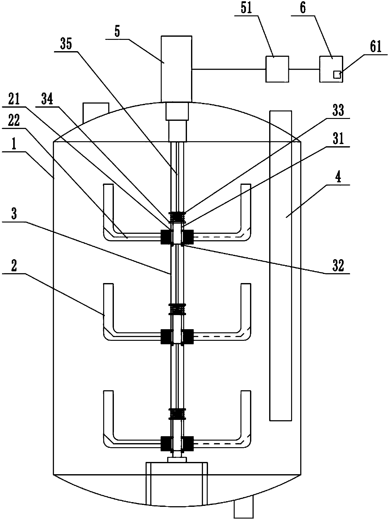
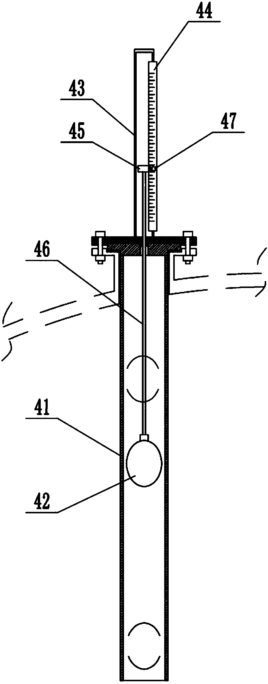
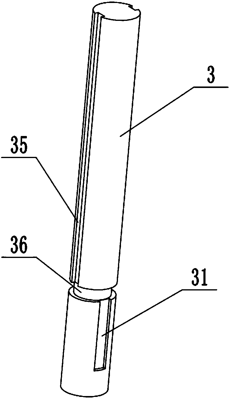
[0030] like figure 1 , figure 2 As shown, the high-concentration waste liquid treatment evaporator in this embodiment includes a tank body 1, in which a stirring shaft 3 with stirring blades 2 is installed and a liquid level detection device 4 is installed, and the stirring shaft 3 passes through the tank body 1 Driven by the stirring motor 5 at the top, the liquid level detection device 4 includes a float tube 41 inserted in the tank body 1, a float ball 42 floating in the float tube 41, installed on the top of the float tube 41 and placed in the tank body 1 outside the scale tube 43, the magnetic induction scale 44 installed on the outside of the scale tube 43, the scale tube 43 is provided with a magnetic block 45 that can move up and down, and the magnetic block 45 is connected to the floating ball 42 through a connecting rod 46; the s...


PUM


Abstract

The invention relates to a high-concentration waste liquid treatment evaporator, which comprises a tank body, wherein a stirring shaft with stirring blades, and a liquid level detection device are arranged in the tank body; the stirring shaft is driven by a stirring motor at the top of the tank body; the liquid level detection device comprises a floating ball tube inserted into the tank body, a floating ball floating in the floating ball tube, a ruler tube which is mounted at the top end of the floating ball tube and is arranged outside the tank body, and a magnetic induction ruler mounted onthe outer side of the ruler tube; a magnetic block capable of moving up and down is arranged in the ruler tube; the magnetic block is connected with the floating ball through a connection rod; multiple groups of stirring blades are arranged up and down in a spacing manner; the stirring blades and the stirring shaft are mounted in an axial sliding manner. According to the high-concentration waste liquid treatment evaporator, by the adoption of a magnetic flap type liquid level detection device, the shortcomings that detection cannot be realized due to crystallization and a conventional ultrasonic liquidometer is inaccurate in detection due to stirring of internal liquid can be overcome; by the adoption of the stirring blades capable of floating up and down, the stirring resistance can be reduced in time, and the stirring effect is enhanced.

Description

technical field [0001] The invention relates to an evaporator, in particular to an evaporator for treating high-concentration waste liquid. Background technique [0002] Evaporators are widely used in chemical industry, food industry. In the pharmaceutical and other industrial fields, it is mainly used to concentrate dilute solutions to directly produce products or to process concentrated solutions into solid products; to concentrate solutions and recover solvents; to obtain pure solvents, etc. [0003] At present, when the evaporator is used for high-salinity waste liquid, the liquid evaporates completely, and the remaining salt concentrate is discharged. After the discharge, the temperature drops to room temperature and the salt precipitates out. [0004] The application number is 2012203081685, and the name is a patent for a high-efficiency enamel evaporator. In the disclosed technical solution, since the evaporator is an enamel reaction equipment, it is airtight and opa...

Claims


Application Information

Patent Timeline
Patent Type & Authority Applications(China)
IPC IPC(8): B01J19/18B01D9/02
CPCB01D9/0018B01J19/18
Inventor 张益
Owner 苏州浩长空环保科技有限公司
Why Eureka
Try Eureka