Initial positioning system and method for fluid flowmeter measuring

A technology for initial positioning and liquid measurement, which is applied in the directions of volume measurement instruments/methods, chemical instruments and methods, liquid/fluid solid measurement, etc. Large-scale promotion and application of containers and other issues

Pending Publication Date: 2018-04-13
BEIJING RED SEA TECH
View PDF4 Cites 2 Cited by
  • Summary
  • Abstract
  • Description
  • Claims
  • Application Information

AI Technical Summary

Problems solved by technology

[0003] However, the existing self-metering containers are affected by factors such as operating strength, operating speed, liquid volume in the main body of the container, and gas volume in the pressure-transforming component during metering and taking, so it is difficult to fix the initial position of the

Method used


Image

  • Initial positioning system and method for fluid flowmeter measuring
  • Initial positioning system and method for fluid flowmeter measuring
  • Initial positioning system and method for fluid flowmeter measuring

Examples


Embodiment 1

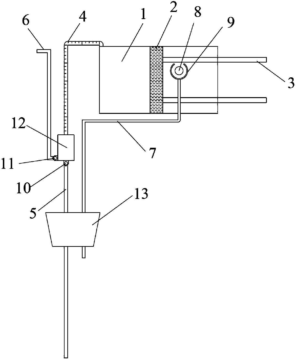
[0030] figure 1 Shown is a schematic structural view of a metering tool including an initial positioning system for liquid metering and taking according to Embodiment 1. The initial positioning system of the metering tool includes a variable pressure chamber 1 , a piston 2 , an operating rod 3 , a metering channel 4 and a pressure relief port 8 . Among them, the piston 2 is located at the horizontal side of the variable pressure chamber 1, the metering channel 4 is connected to the upper part of the variable pressure chamber 1, and the pressure relief port 8 is located at the middle and upper part of the horizontal position of the variable pressure chamber 1, passing through the wall of the variable pressure chamber 1, when the piston 2 reciprocates It can cross the pressure relief port 8 and reach the right side of the pressure relief port 8. When the piston 2 is located at the position of the pressure relief port 8 and the inside and outside of the variable pressure chamber...

Embodiment 2

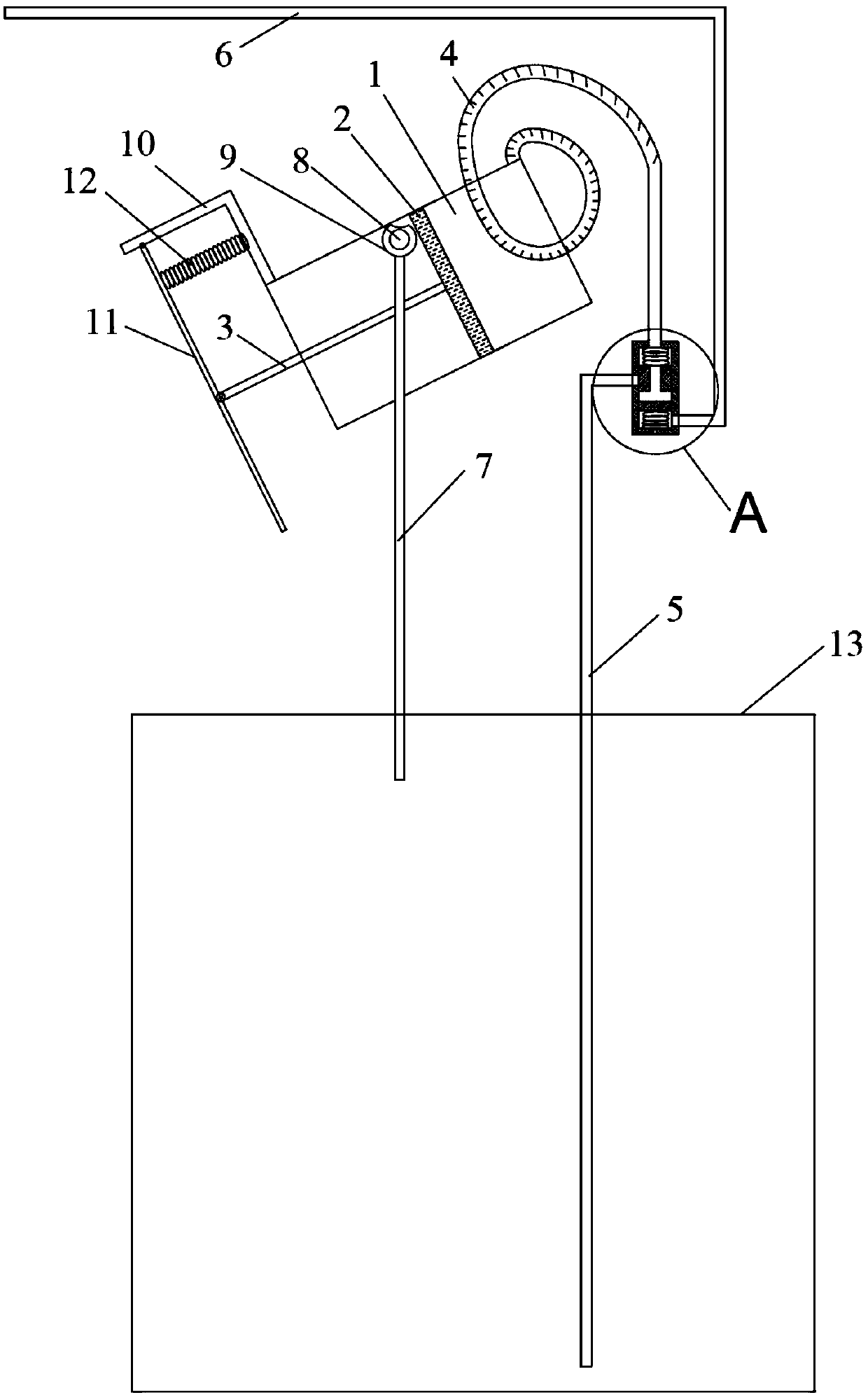
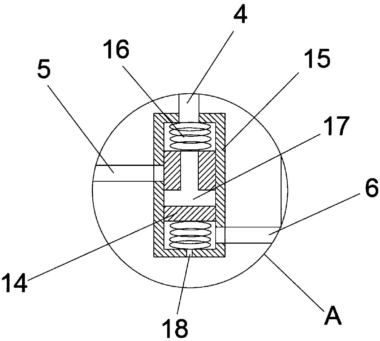
[0038] figure 2 Shown is a schematic structural view of the liquid metering and taking container according to embodiment 2, image 3 It is a partially enlarged view of the liquid metering and taking container A described in Example 2.

[0039] The liquid metering and taking container includes an initial positioning system composed of a pressure-changing chamber 1, a piston 2, a connecting rod 3, a metering channel 4, and a pressure relief port 8, and also includes a bowl 9 covering the outside of the pressure relief port 8, a backflow Channel 7, liquid intake channel 5, outflow channel 6, steering valve and container main body 13, as well as facilities for convenient access operation, including bracket 10 fixed on the outer wall of pressure-transforming chamber 1, movable link with bracket 10 and connecting rod 3 An operating rod 11, a spring 12 located between the bracket 10 and the operating rod 11.

[0040] Among them, the piston 2 is located obliquely below the variable...

Embodiment 3

[0051] Figure 4 Shown is a schematic structural view of a liquid metering and taking container according to Embodiment 3. The liquid metering and taking container includes an initial positioning system composed of a pressure-changing chamber 1, a piston 2, a connecting rod 3, a metering channel 4, and a pressure relief port 8 that opens a valve under a certain pressure. 8 The external return channel 7, the upper part of the return channel 7 is provided with an opening 9, the liquid intake channel 5 and its internal one-way valve 10, the outflow channel 6 and its internal one-way valve 11, the container main body 13, and the electric device connecting the connecting rod 3 12.

[0052] Among them, the piston 2 is located below the pressure changing chamber 1, the metering channel 4 is connected to the upper right part of the pressure changing chamber 1, and the pressure relief port 8 is located at the lower part of the horizontal position of the pressure changing chamber 1, an...


PUM


Abstract

The invention discloses an initial positioning system for fluid flowmeter measuring. The initial positioning system comprises a metering channel, a transformation cavity, a piston; the initial end ofthe metering channel is connected to the upper part of the transformation cavity; a piston is in reciprocating motion in the transformation cavity to make the transformation cavity generate the positive and negative pressure change; meanwhile, the initial positioning system further comprises a pressure release opening located on the wall of the transformation cavity and connected to the outer partof the transformation cavity; the piston performs the reciprocating motion to pass through the pressure release opening; when the piston is located at the pressure release opening, and the inside andoutside of the transformation cavity are connected, the maximum volume of fluid held in the transformation cavity is not less than one third of the total volume of the transformation cavity. The initial positioning system is simple in operation and convenient to measure; the taking process does not use external tools, thus the initial positioning system can prevent fluid from waste, pollution andoxidization, prevent fluid from volatilization or moisture absorption, and improve the sensitivity of metering and using.

Description

technical field [0001] The invention relates to an initial positioning system for liquid metering and taking, a tool and a container using the initial positioning system for liquid metering and taking, and an initial positioning method for liquid metering and taking. Background technique [0002] When people use liquids in their daily lives, they often need to accurately measure the volume of liquids, such as measuring and taking various reagents, liquid pesticides, chemical raw materials, washing liquids, sterilization liquids, edible oils, liquid medicines, etc. To measure these liquids, measuring tools are usually used, such as measuring cylinders, measuring cups, and pipettes. There are many disadvantages in the use of traditional measuring tools, such as waste and pollution caused by the contact of liquids with measuring tools; toxic liquids volatilize; liquids are oxidized by air; loss during transfer affects measurement accuracy, etc. For this reason, there are new t...

Claims


Application Information

Patent Timeline
IPC IPC(8): B01L3/02G01F19/00
CPCG01F19/00B01L3/0293B01L2200/0605
Inventor 陈增新周长春李生录陈景哲陈斌李陈魏浩
Owner BEIJING RED SEA TECH
Why Eureka
Try Eureka