
Unmanned vehicle route tracking control method based on skid turn and slippage coupling estimation

An unmanned vehicle and control method technology, which is applied in the field of unmanned vehicle path tracking control based on slip-slip coupling estimation, can solve the problems of unrealizable, unable to calculate the slip-slip amount, tracking and other problems from time to time.

Active Publication Date: 2018-04-13
HEFEI INSTITUTES OF PHYSICAL SCIENCE - CHINESE ACAD OF SCI
View PDF4 Cites 14 Cited by
  • Summary
  • Abstract
  • Description
  • Claims
  • Application Information

AI Technical Summary

Problems solved by technology

[0003] At present, in the field of unmanned vehicle trajectory tracking, the control method is based on the vehicle kinematics model in a rational state, that is, the vehicle kinematics model under the condition that the wheels of the unmanned vehicle are assumed to have no slip and no slip. However, there is no In the actual road conditions of human-driven vehicles, the wheels generally have slip and slip, especially when unmanned vehicles are driving on gravel roads, ice and snow roads. Therefore, the kinematics model based on the ideal state cannot be calculated from time to time out of slippage, so it is impossible to effectively and accurately track the desired trajectory

Method used


Image

  • Unmanned vehicle route tracking control method based on skid turn and slippage coupling estimation
  • Unmanned vehicle route tracking control method based on skid turn and slippage coupling estimation
  • Unmanned vehicle route tracking control method based on skid turn and slippage coupling estimation

Examples


Embodiment Construction

[0060] A kind of unmanned vehicle path tracking control method based on slip-slip coupling estimation of the present invention will be further described below in conjunction with accompanying drawings and specific embodiments:

[0061] The unmanned vehicle involved in the present invention is an unmanned vehicle with independent full drive, no active steering freedom of the wheels, and the unmanned vehicle with the same wheel speed on the same side of the vehicle body. This unmanned vehicle includes a GPS-INS combined positioning system, The encoder used to collect wheel speed data and the vehicle controller to send the drive motor speed to the vehicle controller.

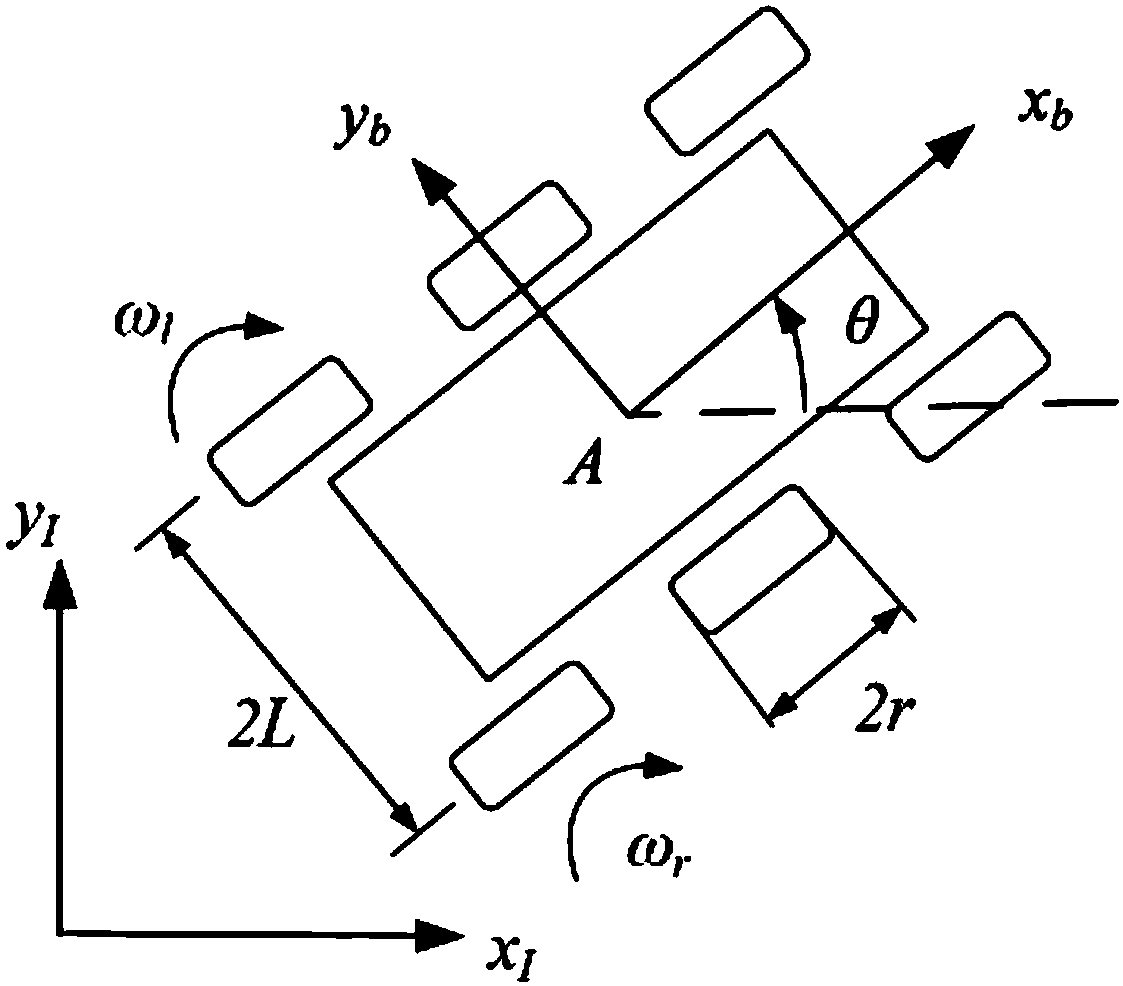
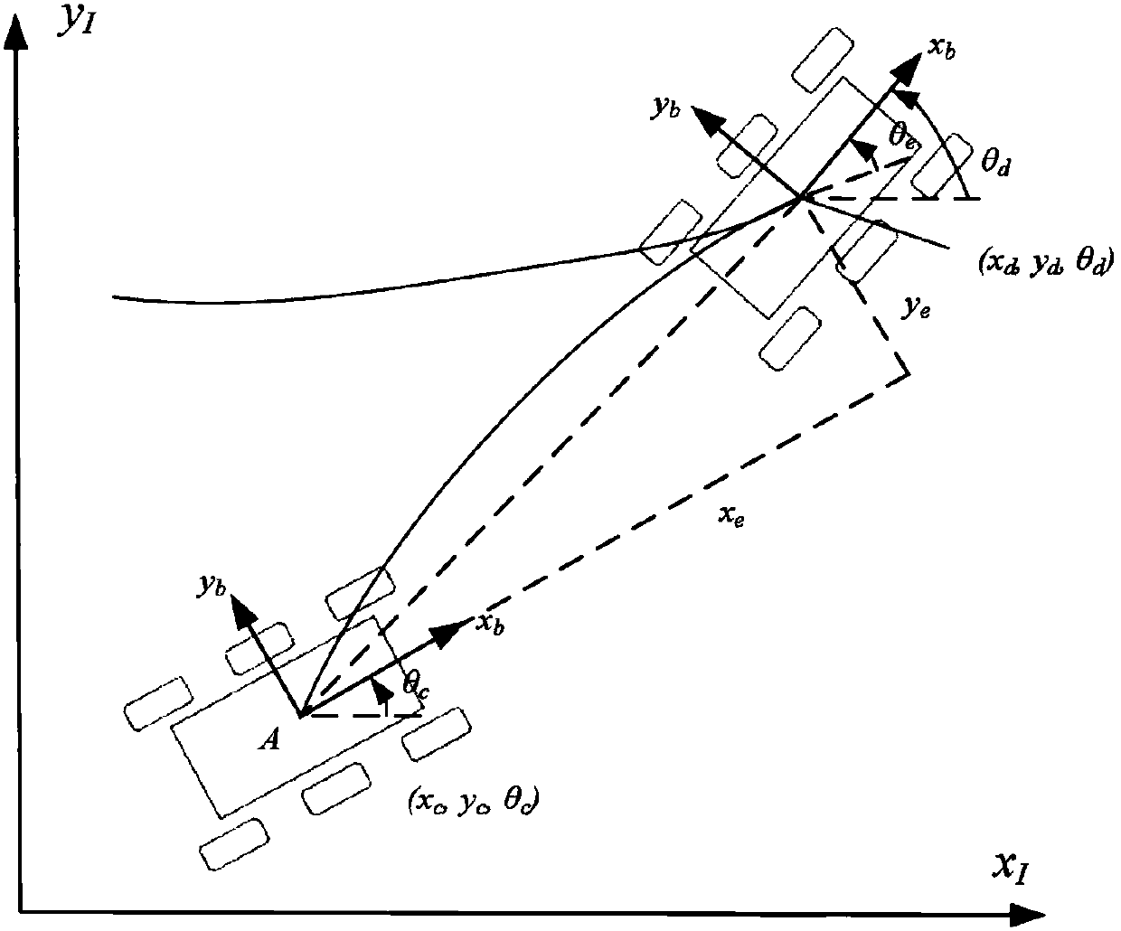
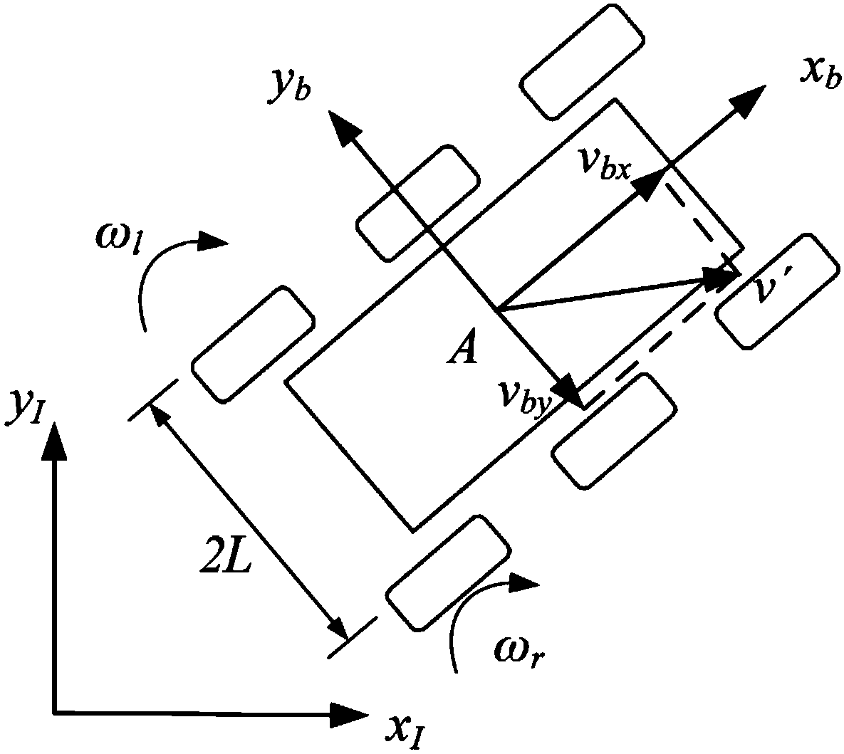
[0062] Such as figure 1 , figure 2 , image 3 with Figure 4 Shown, the present invention is a kind of unmanned vehicle path tracking control method based on skid-slip coupling estimation, and this method comprises the following steps:

[0063] Step 1: Receive the expected trajectory and the expected trajector...


PUM


Abstract

The invention discloses an unmanned vehicle route tracking control method based on skid turn and slippage coupling estimation. By the adoption of the method, according to a motion mathematical model expression of a skid turn coefficient and the slip rate, data detected by an GPS-INS, and an expected route, the expected speed and expected yaw velocity information which are given by an unmanned vehicle decision making level, numerical values of the skid turn coefficient and the slip rate are calculated and then reversely substituted to a kinematic model of an unmanned vehicle, the wheel rotationspeed achieving trajectory tracking is obtained through compensation and calculation, and the purpose of accurate tracking of an expected trajectory is achieved. The method has the beneficial effectsthat the skid turn and slippage amount can be calculated in real time, the actual motion state of the unmanned vehicle is described and represented more really and accurately, and the expected trajectory can be tracked effectively and accurately.

Description

Technical field: [0001] The invention relates to the technical field of unmanned vehicles, in particular to an unmanned vehicle path tracking control method based on slip-slip coupling estimation. Background technique: [0002] As an important direction and trend of future vehicle development, unmanned vehicles have attracted the attention and development of many research institutions and enterprises in the world. Among the key technologies of vehicle control for unmanned vehicles, path tracking control is the core technical method for unmanned vehicles to drive according to the path planning. The path expected to reach the specified destination. [0003] At present, in the field of unmanned vehicle trajectory tracking, the control method is based on the vehicle kinematics model in a rational state, that is, the vehicle kinematics model under the condition that the wheels of the unmanned vehicle are assumed to have no slip and no slip. However, there is no In the actual ro...

Claims


Application Information

Patent Timeline
IPC IPC(8): B60W50/00B60W40/10
CPCB60W40/10B60W50/00B60W2050/0043
Inventor 梁华为张辉刘跃陶翔丁祎丁骥徐照胜
Owner HEFEI INSTITUTES OF PHYSICAL SCIENCE - CHINESE ACAD OF SCI
Learn More