Grab chip structure of a chip burner

A chip structure and burner technology, which is applied to conveyor objects, transportation and packaging, etc., can solve problems such as low equipment work efficiency, and achieve the effects of improving accuracy, shortening assembly time, and improving work efficiency.

Active Publication Date: 2020-11-03
群沃电子科技(苏州)有限公司
View PDF6 Cites 0 Cited by
  • Summary
  • Abstract
  • Description
  • Claims
  • Application Information

AI Technical Summary

Problems solved by technology

[0003] In the existing technology, the nozzle of the chip burner needs to move the chip from the feeding area to the working area above the CCD camera every time during the process of picking and placing the chip, and then move to the burning area. In the Y direction, The mechanical arm needs to move back and forth twice, resulting in low efficiency of the equipment

Method used


Image

  • Grab chip structure of a chip burner
  • Grab chip structure of a chip burner

Examples


Embodiment

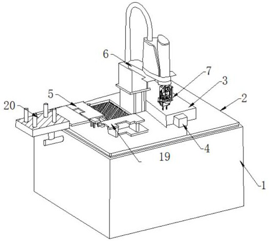
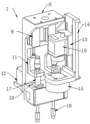
[0018] Such as Figure 1-2 As shown, a grabbing chip structure of a chip burning machine includes a Z-axis module 7, a four-axis robot arm 6 is installed above the Z-axis module 7, and a tray loading mechanism placement area 5 is provided below the four-axis robot arm 6 , And the disc loading mechanism placement area 5 is set on the console 2, the upper side panel of the console 2 is connected with the burning area 3, the burning area 3 side is provided with a tray replenishment tray 19, and the burning area 3 side The lower CCD camera working area 4 is connected. The Z-axis module 7 includes a Z-axis mounting plate 8. A Z-direction pneumatic cylinder 9 is provided under the Z-axis mounting plate 8. The lower end of the Z-direction pneumatic cylinder 9 is connected with a fixed plate 11, which is connected to the fixed plate 11 There is a chip pressing rod 17, a burning table 10 is arranged under the chip pressing rod 17, and one side of the burning table 10 is connected with t...


PUM


Abstract

The invention discloses a chip grabbing structure of a chip burning machine. The chip grabbing structure of the chip burning machine comprises a Z-axle module; a four-axle robot arm is mounted above the Z-axle module; a disc loading feed mechanism placing area is arranged below the four-axle robot arm, and is arranged on a console; an upper side panel of the console is connected with a burning area; one side of the burning area is connected with a lower CCD camera working area; the Z-axle module comprises a Z-axle mounting plate; and a Z-directional pneumatic cylinder is arranged below the Z-axle mounting plate. The chip grabbing structure of the chip burning machine has the following beneficial effects: the Z-axle module and an upper CCD are fixed on the robot arm, so that a robot realizes active positioning and quick grabbing of chips through an upper CCD visual system; the four-axle robot can realize several-axle linkage, and cooperates with a fly shooting technology of the CCD to greatly improve the working efficiency of equipment and to further improve the precision; and in addition, the robot is used for replacing a traditional three-axle motion platform to simplify the partstructure of the equipment, the equipment assembly time can be shortened, and the workshop equipment capacity is improved.

Description

Technical field [0001] The present invention relates to the technical field of chip burning, in particular to a grabbing chip structure of a chip burning machine. Background technique [0002] The burner is actually a tool for writing data on programmable integrated circuits. The burner is mainly used for programming (or flashing) chips such as single-chip microcomputer (including embedded) / memory (including BIOS). [0003] In the prior art, the nozzle of the chip burning machine moves the chip from the feeding area to the working area above the CCD camera each time during the picking and placing process of the chip, and then moves to the burning area, in the Y direction, The mechanical arm needs to move back and forth two times, resulting in low efficiency of the equipment. Summary of the invention [0004] The technical problem to be solved by the present invention is to overcome the defects of the prior art and provide a grabbing chip structure of a chip burning machine. [0005]...

Claims


Application Information

Patent Timeline
Patent Type & Authority Patents(China)
IPC IPC(8): B65G47/91
CPCB65G47/914B65G47/917
Inventor 周光杰
Owner 群沃电子科技(苏州)有限公司
Why Eureka
Try Eureka