
Self-priming pump

A technology of self-priming pumps and pump shafts, applied in pumps, rotary piston pumps, rotary piston machines, etc., can solve problems affecting the normal use of pumps

Inactive Publication Date: 2018-04-13
慈溪市嘉驰电器有限公司
View PDF0 Cites 0 Cited by
  • Summary
  • Abstract
  • Description
  • Claims
  • Application Information

AI Technical Summary

Problems solved by technology

Therefore, due to the existence of axial force, the normal use of the pump has been seriously affected

Method used


Image

  • Self-priming pump

Examples


Embodiment Construction

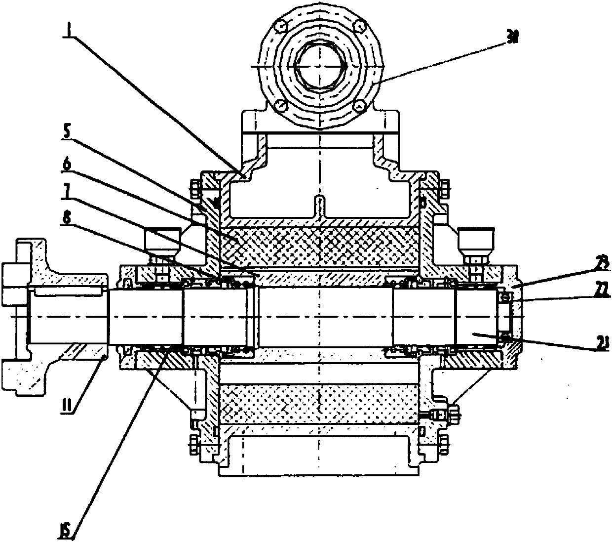
[0006] figure 1 As shown, the inner curve of the pump body 1 is composed of circular arcs and constant acceleration curves. There are suction and discharge ports in the radial direction. The suction port is connected with the pump inlet, and the liquid discharge port is connected with the pump outlet. There is a groove, and it is shrunk on the pump shaft 21. The sliding plate 6 is installed in the groove, and they are installed eccentrically in the pump body 1. The pump shaft 21 is positioned by the double needle roller bearing 15 whose two ends are installed on the pump bearing end cover 5. A flat bearing 22 is installed at the end of the pump shaft cover 23, two mechanical seals 8 are used for the shaft end seal, a safety valve 30 is installed on the upper part of the pump body 1, and a coupling 11 at the end of the pump shaft 21 is formed to form a new type of sliding vane self-priming pump .


PUM


Abstract

The invention relates to a self-priming pump. The inner curve of the pump body 1 is composed of circular arcs and constant acceleration curves. There are suction and discharge ports in the radial direction. The liquid suction port is connected with the pump inlet, and the liquid discharge port is connected with the pump outlet. , the inner rotor 7 is radially grooved, and is shrunk on the pump shaft 21, and the sliding plate 6 is installed in the groove, and is installed eccentrically in the pump body 1. The pump shaft 21 is supported by the two-end pump bearing cover 5, and the shaft end adopts Two mechanical seals 8, the pump shaft 21 is radially positioned by double needle roller bearings 15 installed on the pump bearing end cover 5, the axial direction is positioned by plane bearings 22, the upper part is equipped with a safety valve 30, and the pump shaft 21 is extended. Install shaft coupling 11 to form a novel vane self-priming pump. After the planar bearing 22 is designed, the axial movement of the pump is limited, and the friction and wear between the end surface of the inner rotor 7 and the end surface of the pump bearing end cover 23 caused by axial movement is avoided, which achieves a practical purpose and improves the petrochemical industry equipment. Economical and reliable use.

Description

technical field [0001] The invention relates to a self-priming pump. Background technique [0002] In the existing vane self-priming pump, the pump shaft is positioned by the double-needle roller bearings installed on the end cover of the pump bearing at the two ends. The pump shaft is in a floating state during operation. The friction and wear between the end face of the inner rotor on the pump and the end face of the pump bearing cover, and this process will intensify with the operation of the pump. This is because with the friction and wear between the end face of the inner rotor and the end face of the pump bearing cover, the gap on the back increases, thereby increasing the pressure on the back, further increasing the axial force, and aggravating the friction and wear. This process will cause damage to the pump parts in a short time, affecting the normal use of the pump. However, the axial force is unavoidable when the pump is working. This is because, due to the non-...

Claims


Application Information

Patent Timeline
Patent Type & Authority Applications(China)
IPC IPC(8): F04C2/344
CPCF04C2/344
Inventor 方新土
Owner 慈溪市嘉驰电器有限公司
Learn More