
Positioning device for processing box limit hole of reset box in flexible socket of charging pile

A positioning device and charging pile technology, applied in positioning devices, metal processing equipment, metal processing machinery parts, etc., can solve problems such as affecting production efficiency, increasing the labor intensity of operators, and achieving the effect of improving stability

Active Publication Date: 2021-11-16
吉安市惠安建材有限公司
View PDF8 Cites 0 Cited by
  • Summary
  • Abstract
  • Description
  • Claims
  • Application Information

AI Technical Summary

Problems solved by technology

At present, due to the lack of special devices, when producing the reset front cover, it is mostly measured manually and then punched (box limit hole), and then the circumferential position of the reset front cover is manually adjusted to achieve it. Assembling the ring body, it can be seen that this operation method will not only increase the labor intensity of the operator, but also greatly affect the production efficiency

Method used


Image

  • Positioning device for processing box limit hole of reset box in flexible socket of charging pile
  • Positioning device for processing box limit hole of reset box in flexible socket of charging pile
  • Positioning device for processing box limit hole of reset box in flexible socket of charging pile

Examples


Embodiment 1

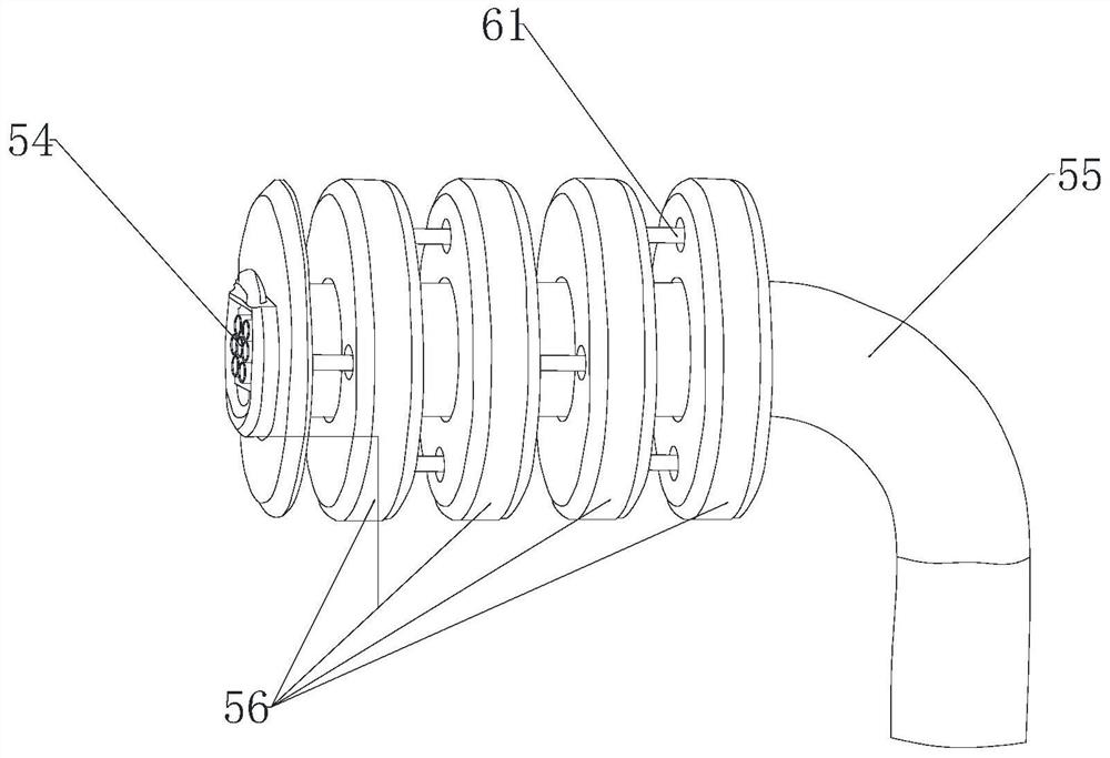
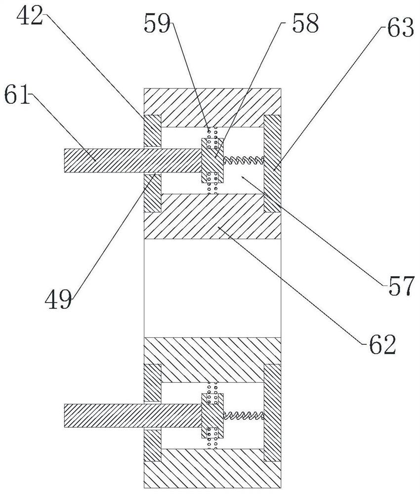
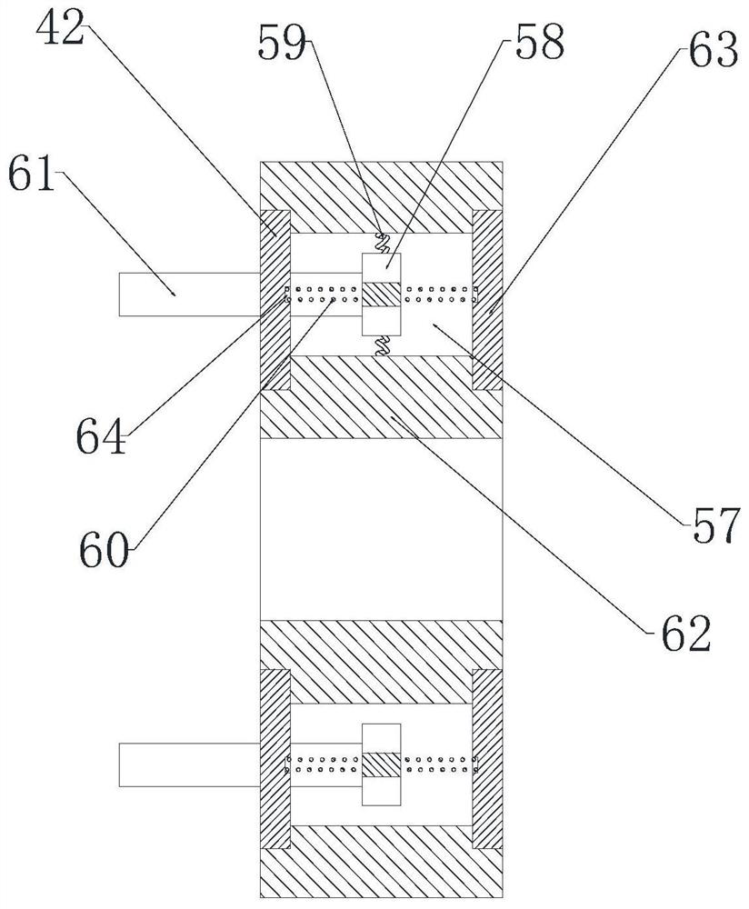
[0062] Such as Figure 1 to Figure 16 As shown, the positioning device for processing the box limit hole of the reset box in the flexible socket of the charging pile includes a positioning seat 1;

[0063] The positioning support seat 1 is connected with a positioning support seat 2, and the positioning support seat 2 is connected with a positioning linkage seat 4 located above the positioning support seat 2 through the first support seat connecting rod 3;

[0064] The bottom end of the positioning linkage seat 4 is provided with two symmetrically arranged linkage seat abutment columns 7;

[0065] The area between the positioning support seat 2 and the positioning linkage seat 4 is also provided with a positioning lower pressure seat 5, and the positioning lower pressure seat 5 is provided with an arc-shaped opening 15 for the lower pressure seat connecting rod 3 to give way to the first support seat. The connecting rod 3 of the first supporting seat can move relative to the ...

Embodiment 2

[0074] This embodiment makes the following further limitations on the basis of Embodiment 1: the bottom end of the positioning protrusion 14 of the positioning lower pressure seat 5 is provided with a downwardly convex elastic abutment section 41 of the lower pressure seat;

[0075] The support seat elastic assembly includes at least two support seat abutment grooves 6 provided on the positioning support seat 2, the support seat abutment groove 6 has a large opening and a small inner cavity;

[0076] The supporting base elastic assembly also includes at least two second supporting base connecting rods 8 that can respectively pass through the openings of the corresponding supporting base abutting grooves 6 , and the bottom end of the second supporting base connecting rods 8 is connected with a connecting rod located in the supporting base abutting groove 6 The inner connecting rod anti-off head 9;

[0077] At least two second support seat connecting rods 8 are connected with th...

Embodiment 3

[0084] In this embodiment, the following further limitations are made on the basis of Embodiment 1: the top end of the positioning support seat 2 is provided with a support plate receiving groove 21 capable of accommodating the support plate 19 of the lower pressing seat.

[0085] In this embodiment, the support plate receiving groove 21 is provided for accommodating the support plate 19 of the lower press seat, so that the positioning of the lower press seat 5 can be ensured to have sufficient downward movement.


PUM


Abstract

The invention discloses a positioning device for processing a box limit hole of a resetting box in a flexible socket of a charging pile, comprising a positioning seat; a positioning support seat is connected to the positioning seat; two symmetrical The set linkage seat abuts against the column; the area between the positioning support seat and the positioning linkage seat is also provided with a positioning lower pressing seat, and a lower pressing seat arc for giving way to the connecting rod of the first supporting seat is provided on the positioning lower pressing seat The abutment groove of the lower pressure seat has a deep part of the abutment groove and a shallow part of the abutment groove. The groove depth from the shallow part of the abutment groove to the deep part of the abutment groove is gradually positioned along the circumferential direction of the lower pressure seat. Deepening; a positioning drive assembly for driving the rotation of the positioning lower press seat is also installed on the positioning placement seat. Through the setting of the positioning support seat and the positioning lower pressure seat, and the cooperation between the abutment groove of the lower pressure seat and the abutment column of the linkage seat, the present invention can perform stable positioning work on the circumferential position of the workpiece to be processed, so as to prepare for subsequent accurate hole punching operation.

Description

technical field [0001] The invention belongs to the technical field of charging pile machining, and in particular relates to a positioning device for processing a box limit hole of a reset box in a charging pile flexible socket. Background technique [0002] With the popularity of electric vehicles, the demand for the number and function of electric vehicle charging piles is gradually increasing. In practice, in order to improve the service life of charging pile sockets, some manufacturers have designed flexible sockets, such as Figure 1 to Figure 5 As shown, the flexible socket includes a charging socket and a charging pile connection line connected to the charging socket. The outer wall of the charging pile connection line is evenly set with several sets of reset boxes, and each reset box is symmetrically provided with two sets of reset cavities. , the reset box is also provided with a box limit hole connected with the reset cavity, a reset positioning block is arranged i...

Claims


Application Information

Patent Timeline
Patent Type & Authority Patents(China)
IPC IPC(8): B23B41/00B23B47/00B23Q3/06B23Q11/08
CPCB23B41/00B23B47/00B23Q3/06B23Q11/08
Inventor 张雪松
Owner 吉安市惠安建材有限公司
Learn More