Accurate clamping and punching equipment for supporting foot part

A technology for drilling equipment and parts, which is applied in the direction of drilling/drilling equipment, metal processing equipment, metal processing machinery parts, etc. It can solve the problems of unfavorable large-scale production, high manual labor intensity, and inaccurate positioning and drilling. Achieve the effect of reducing labor intensity, improving work efficiency and improving precision

Inactive Publication Date: 2020-12-04
方剑
View PDF0 Cites 1 Cited by
  • Summary
  • Abstract
  • Description
  • Claims
  • Application Information

AI Technical Summary

Problems solved by technology

[0005] In order to solve the above-mentioned technical problems, a precise clamping and drilling device for supporting foot parts is provided. This technical solution solves the traditional method of manually clamping the workpiece and drilling it with a handheld drilling device. This operation method is not accurate enough for positioning and punching, the labor intensity is high, and it is not conducive to large-scale production.

Method used


Image

  • Accurate clamping and punching equipment for supporting foot part
  • Accurate clamping and punching equipment for supporting foot part
  • Accurate clamping and punching equipment for supporting foot part

Examples


Embodiment Construction

[0025] The following description serves to disclose the present invention to enable those skilled in the art to carry out the present invention. The preferred embodiments described below are only examples, and those skilled in the art can devise other obvious variations.

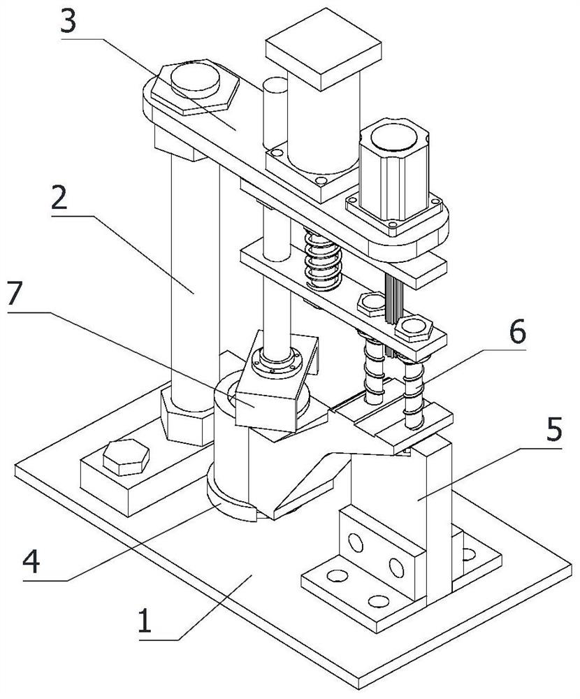
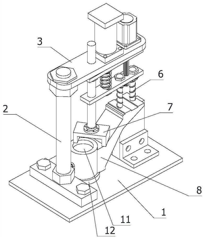
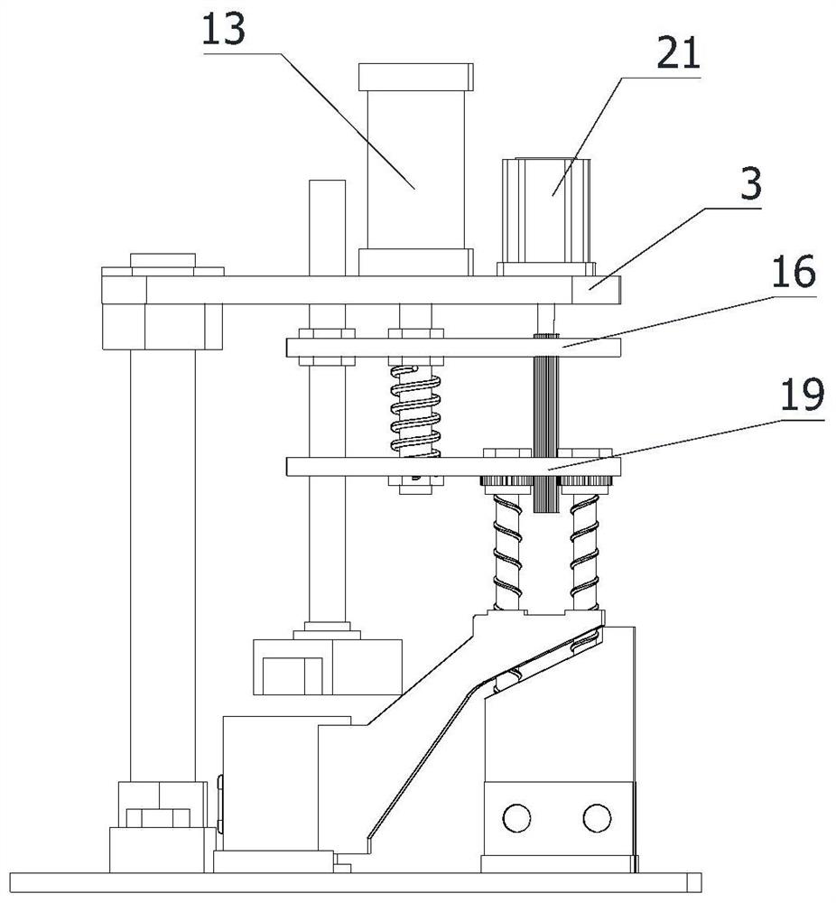
[0026] refer to Figure 1-Figure 7 A precision clamping and punching equipment for standoff parts shown includes a frame 1, a vertical mounting column 2, a horizontal mounting plate 3, a part positioning seat 4, a drilling bearing seat 5, a drilling bit 6, a clamp Holding the fixed claw 7, the rotary driving mechanism, the pressing driving mechanism and the supporting foot part 8, the frame 1 is horizontally arranged, the vertical mounting column 2 is vertically fixedly installed on the top side of the frame 1, and the horizontal mounting plate 3 is horizontally arranged on the machine frame. Directly above the frame 1, one end of the horizontal mounting plate 3 is fixedly connected to the top of the vertic...


PUM


Abstract

The invention relates to the technical field of machining, in particular to accurate clamping and punching equipment for a supporting foot part. The equipment comprises a rack, a vertical mounting column, a horizontal mounting plate, a part positioning seat, a drilling bearing seat, punching drill bits, a clamping and fixing claw, a rotary driving mechanism, a pressing driving mechanism and the supporting foot part. The part positioning seat comprises a positioning pin which is vertically arranged and used for fixing a cylindrical portion on the supporting foot part, the drilling bearing seatcomprises a vertical bearing plate which is vertically arranged and used for bearing a supporting connecting portion on the supporting foot part, the number of the punching drill bits is two, and thetwo punching drill bits are located over the positions, needing to be drilled, of the supporting connecting portion respectively. According to the accurate clamping and punching equipment for the supporting foot part, a workpiece can be accurately positioned and clamped, accurate punching operation can be conducted on the workpiece, the labor intensity of workers is reduced, the workpiece can be prevented from shaking during machining, the two punching drill bits can conduct drilling operation synchronously, the working efficiency is improved, and the product quality is improved.

Description

technical field [0001] The invention relates to the technical field of mechanical processing, in particular to a device for accurately clamping and punching foot parts. Background technique [0002] During the installation, use, and maintenance of large modules inside the financial self-service equipment cabinet, since the internal modules need to be dragged from the cabinet for installation, use, and maintenance, the general modules are set in the cabinet through trays to facilitate the overall movement. [0003] When processing the standoffs of the cabinet, it is necessary to perform drilling operations on the standoffs. The traditional method is to manually clamp the workpiece and punch it with a hand-held drilling device. This operation method is not enough for positioning and punching. Accurate, labor-intensive, and not conducive to large-scale production. [0004] Therefore, it is necessary to design a kind of accurate clamping and punching equipment for supporting fo...

Claims


Application Information

Patent Timeline
Patent Type & Authority Applications(China)
IPC IPC(8): B23B41/00B23B47/00B23B39/16B23Q3/06
CPCB23B39/16B23B39/161B23B41/00B23B47/00B23Q3/06B23Q3/062
Inventor 方剑
Owner 方剑
Why Eureka
Try Eureka