
A rocking back drill drilling tooling device

A technology of drilling and back-drilling, applied in positioning devices, clamping devices, boring/drilling, etc., can solve the problems of small workpieces and unsuitable for processing large-length workpieces, and achieve high work efficiency and reasonable structural design , the effect of broad market application prospects

Inactive Publication Date: 2017-03-15
HUNAN UNIV OF HUMANITIES SCI & TECH
View PDF6 Cites 0 Cited by
  • Summary
  • Abstract
  • Description
  • Claims
  • Application Information

AI Technical Summary

Problems solved by technology

[0003] This radial drilling machine is widely used in single-piece and small-to-medium batch production to process holes in workpieces with large volume and weight, so the processed workpieces are small and not suitable for processing large-length workpieces

Method used


Image

  • A rocking back drill drilling tooling device
  • A rocking back drill drilling tooling device
  • A rocking back drill drilling tooling device

Examples


Embodiment Construction

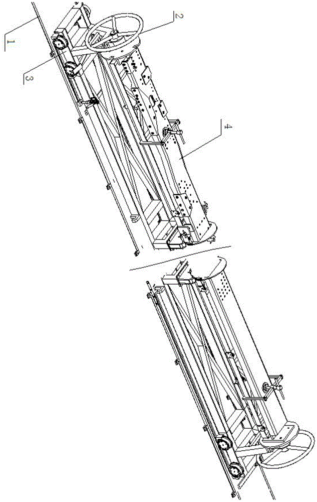
[0030] Such as figure 1 A kind of rocking back drill punching tooling device shown, comprises rail device 1, rotating device 2, mobile trolley device 3 and crossbeam drilling mold cover device 4, and described mobile trolley device 3 is installed on the described rail device 1, so The rotating device 2 is installed on the moving trolley device 3 , and the beam jig set device 4 is installed on the rotating device 2 .

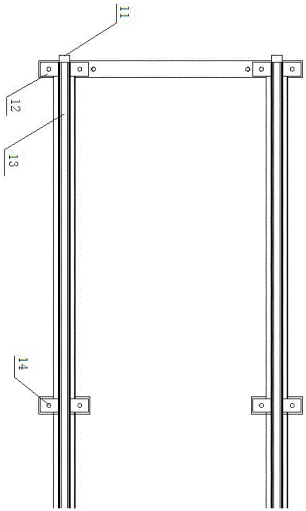
[0031] Such as figure 2 The schematic diagram of the track device structure is shown. This track device 1 comprises light rail 13, and the baffle plate 11 that is installed on the end of described light rail 13, is installed on the rail pressing plate 12 of described light rail 13 side, described rail pressing plate 12 fixes described light rail 13 at intervals, and distance is 900-1000mm, and fixed by expansion screws 14.

[0032] Such as image 3 Schematic diagram of the structure of the rotating device shown. The rotating device includes a rotating body ...


PUM

PropertyMeasurementUnit
lengthaaaaaaaaaa

Abstract

The invention discloses a radial drill drilling fixture device. The radial drill drilling fixture device comprises a rail device, a rotating device, a moving car device and a beam drill die sleeve device, wherein the moving car device is mounted on the rail device; the rotating device is mounted on the moving car device; the beam drill die sleeve device is mounted on the rotating device; the moving car device can drive the rotating device to move horizontally on rails; the rotating device can drive the beam drill die sleeve device to rotate at 360 degrees. The radial drill drilling fixture device is reasonable in structural design, can achieve horizontal movement and 360-degree rotary drilling of large-length beams and has the advantage of being simple in operation, convenient to use and high in working efficiency, thereby being widely applied to efficient, rapid and accurate drilling operation of large-length vehicle beams and having a wide market application prospect.

Description

technical field [0001] The invention belongs to the technical field of equipment manufacturing, and in particular relates to a radial back drilling tooling device for drilling holes on automobile girders. Background technique [0002] The perforating device that generally uses in the prior art is the radial drilling machine, and the radial drilling machine mainly is made up of parts such as base, inner column, outer column, rocking arm, spindle box and workbench. The inner column is fixed on one end of the base, and an outer column is sheathed outside it, and the outer column can rotate 360 ​​degrees around the inner column. One end of the rocker arm is a sleeve, which is set on the outer column to move up and down. Since the screw mandrel is integrated with the outer column, and the lifting nut is fixed on the rocker arm, the rocker arm cannot rotate around the outer column, but can only rotate around the inner column together with the outer column. The spindle box is a c...

Claims


Application Information

Patent Timeline
Patent Type & Authority Patents(China)
IPC IPC(8): B23B47/00B23B47/28B23B41/00B23Q3/00
CPCB23B39/12B23B39/14B23B41/00B23B41/003B23B47/00B23B47/28B23B2247/12B23Q1/015B23Q1/25B23Q3/00B23Q3/062B23Q7/00B23Q7/02B23Q2703/10
Inventor 谭峰亮
Owner HUNAN UNIV OF HUMANITIES SCI & TECH
Learn More