Optical Densitometer for Automatically Measuring Blackness Range and Optical Density Calculation Method

An optical densitometer, automatic measurement technology, applied in computer control, transmittance measurement, program control and other directions, can solve the problems of high labor intensity, black level meter can only measure blackness at a single point, low efficiency, etc. Interfere and improve the effect of automatic measurement efficiency

Active Publication Date: 2019-10-11
ANYANG ZHONGKE ENG TESTING
View PDF7 Cites 1 Cited by
  • Summary
  • Abstract
  • Description
  • Claims
  • Application Information

AI Technical Summary

Problems solved by technology

[0005] In order to overcome the defects existing in the prior art, the object of the present invention is to propose an optical densitometer for automatically measuring the range of blackness in view of the problems of low efficiency, high labor intensity, large measurement error and irregularity of the traditional blackness meter at present. Introducing a linear sensor array to solve the problem that traditional blackness meters can only measure blackness at a single point

Method used


Image

  • Optical Densitometer for Automatically Measuring Blackness Range and Optical Density Calculation Method
  • Optical Densitometer for Automatically Measuring Blackness Range and Optical Density Calculation Method
  • Optical Densitometer for Automatically Measuring Blackness Range and Optical Density Calculation Method

Examples


Embodiment Construction

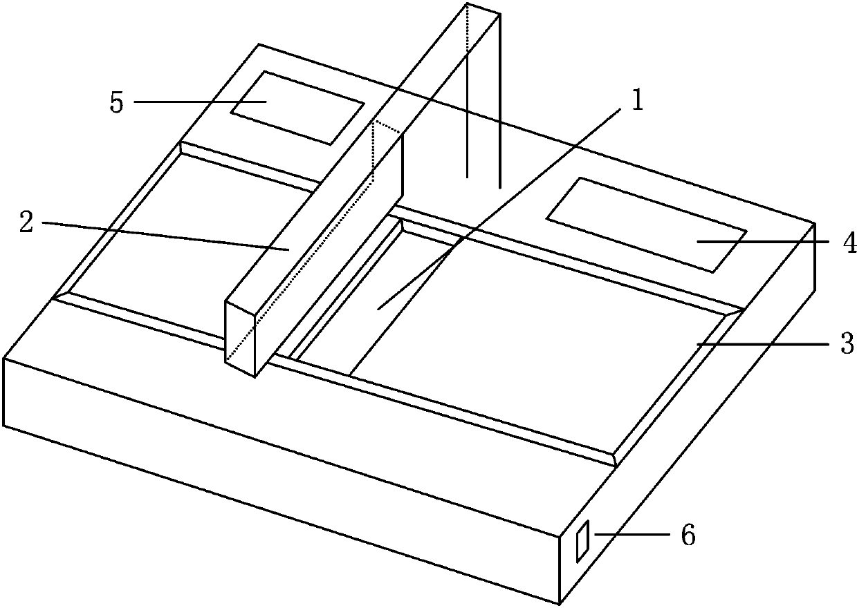
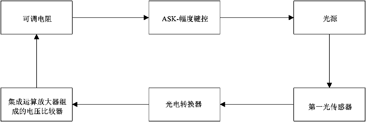
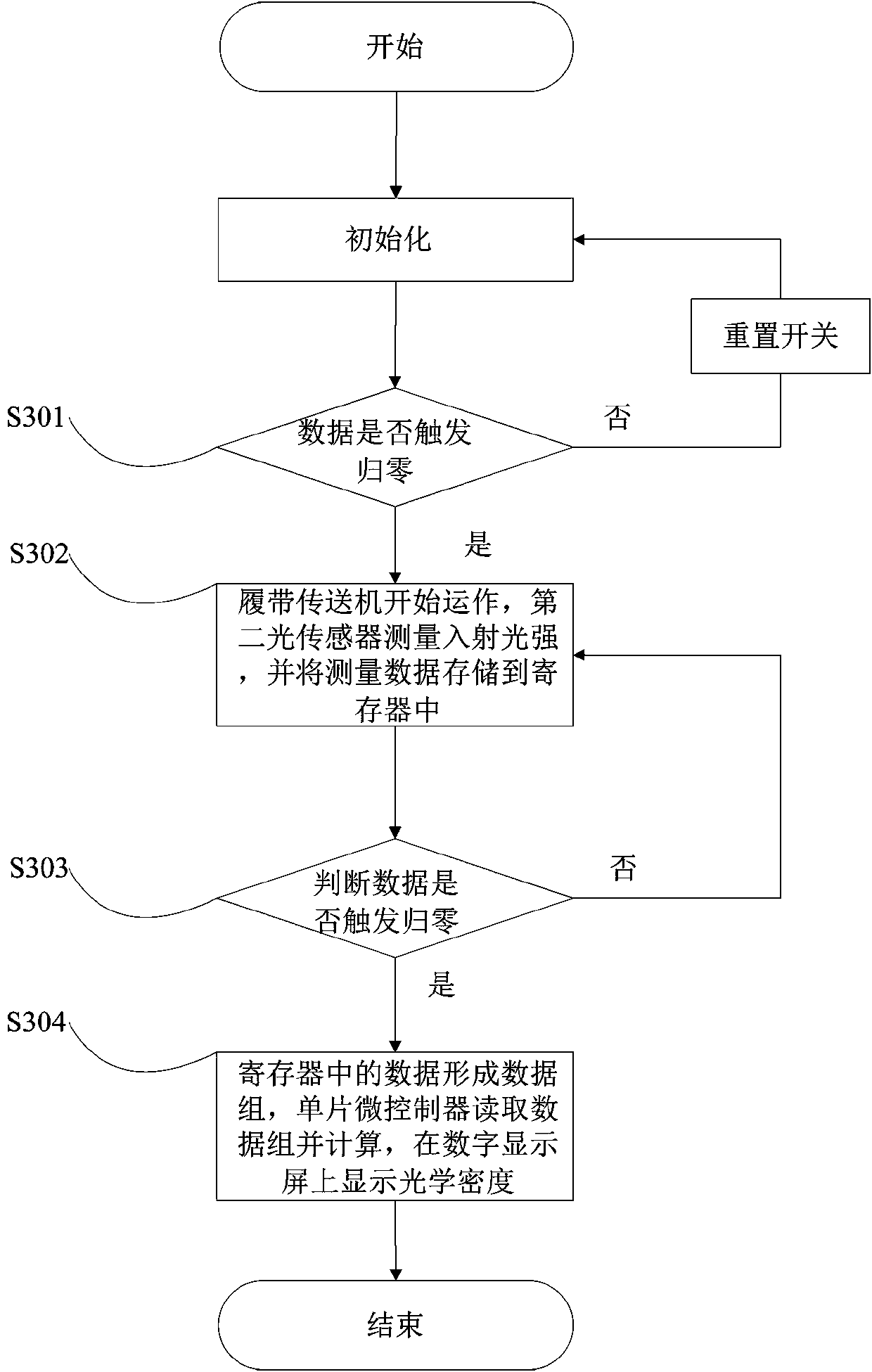
[0030] The core of the present invention is to provide an optical density meter that can automatically measure the range of blackness, introducing a linear sensor array to solve the problem that traditional blackness meters can only measure blackness at a single point; another core of the present invention is to provide an optical density meter. Density calculation method.

[0031] In order to make the objectives, technical solutions, and advantages of the embodiments of the present invention clearer, the technical solutions in the embodiments of the present invention will be described clearly and completely in conjunction with the accompanying drawings in the embodiments of the present invention. Obviously, the described embodiments It is a part of the embodiments of the present invention, not all the embodiments. Based on the embodiments of the present invention, all the embodiments obtained by those of ordinary skill in the art without creative work shall fall within the prote...


PUM


Abstract

The invention belongs to the technical field of nondestructive detection and radiographic testing, and particularly relates to an optical densitometer for automatically measuring density range. The optical densitometer for automatically measuring the density range comprises a light source control system, a light source receiving device, a track conveyor and a central control system, wherein the light source control system and the light source receiving device are oppositely arranged; a plurality of photographic films are arranged between the light source control system and the light source receiving device and positioned on a conveying track of the track conveyor; the central control system is correspondingly and electrically connected to the light source control system, the light source receiving device and the track conveyor. The invention also provides optical density calculation method. According to the optical densitometer for automatically measuring the density range and the optical density calculation method, the problems such as low efficiency, high working intensity, large measuring error and lack of standardization of a traditional densitometer at present can be solved; the concept of a linear sensing array is introduced and free from a single point sensor is avoided, so that the automatic measuring efficiency of a complete photographic plate can be greatly improved.

Description

Technical field [0001] The invention belongs to the technical field of nondestructive testing radiation detection, and particularly relates to an optical densitometer for automatically measuring the range of blackness and an optical density calculation method. Background technique [0002] The optical density meter, also known as the blackness meter, reflects the exposure of the radiographic film and is an important auxiliary equipment for radiography. The measurement of the density of the radiographic film is of great significance in the quality evaluation of the radiographic film. The blackness of radiographic film is measured with a transmission blackness meter. [0003] Currently, the digital display blackness meter is widely used. Its structure principle converts the received analog light signal into a digital electrical signal. Because its structure is a single light sensor structure, it can only measure the single-point blackness value within the evaluation range. If measur...

Claims


Application Information

Patent Timeline
Patent Type & Authority Patents(China)
IPC IPC(8): G01N21/59G05B19/042
Inventor 林如意吴红伟娄旭耀郭浩男林茁赵丽李丽董庆锋郭云龙段柯
Owner ANYANG ZHONGKE ENG TESTING
Why Eureka
Try Eureka