Supercharge Your Innovation With Domain-Expert AI Agents!

Display driving method and device

A display driver and display position technology, applied to static indicators, instruments, etc., can solve problems such as uneven charging, color shift, etc., and achieve the effect of improving color shift and charging uniformity

Active Publication Date: 2020-01-31
TCL CHINA STAR OPTOELECTRONICS TECH CO LTD
View PDF6 Cites 0 Cited by
  • Summary
  • Abstract
  • Description
  • Claims
  • Application Information

AI Technical Summary

Problems solved by technology

[0005] However, in the prior art, whether an external IC is used to drive the gate lines or a GOA circuit is used to drive the gate lines, the pulse widths of the gate drive signals generated corresponding to each gate line are the same. Since the distance between the pixels connected to the gate lines of different rows and the source driver chip is different, when the source driver chip charges the pixels far away from the source driver chip through the data line, the charging rate will be lower than that of the pixels far away from the source driver chip. Drive the pixels close to the chip, causing uneven charging and color shift

Method used


Image

  • Display driving method and device
  • Display driving method and device
  • Display driving method and device

Examples


Embodiment Construction

[0035] In order to further illustrate the technical means adopted by the present invention and its effects, the following describes in detail in conjunction with preferred embodiments of the present invention and accompanying drawings.

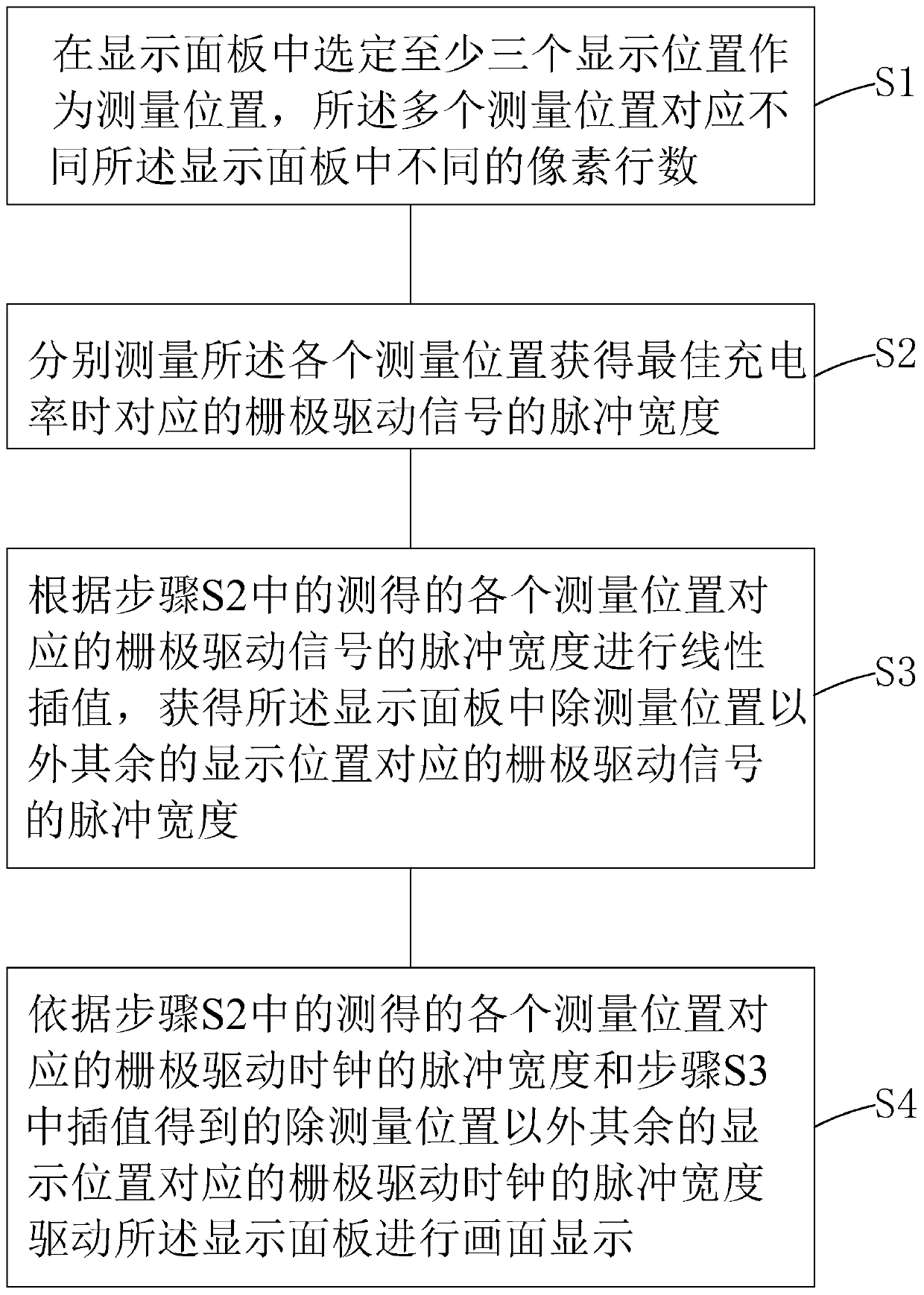
[0036] see figure 1 , the present invention also provides a display driving method, comprising the following steps:

[0037] Step S1 , selecting at least three display positions in the display panel 10 as measurement positions, and the plurality of measurement positions correspond to different numbers of pixel rows in different display panels 10 .

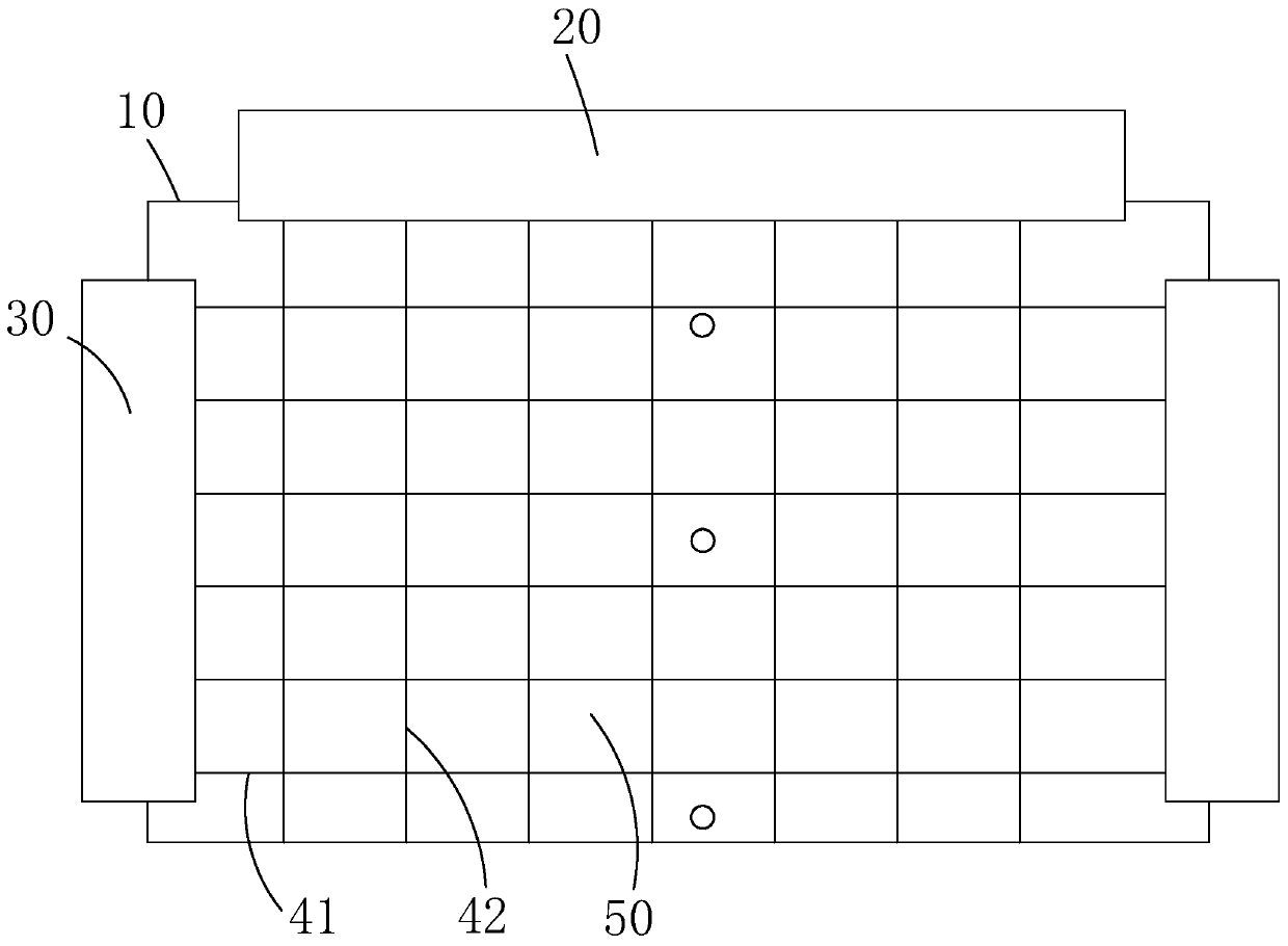
[0038] Specifically, such as figure 2 As shown, the display panel 10 includes: a plurality of gate lines 41 arranged in parallel at intervals, a plurality of data lines 42 arranged in parallel at intervals, and a crossing defined by the plurality of gate lines 41 and the plurality of data lines 42 A plurality of pixels 50 arranged in an array; the plurality of gate lines 41 are electrically conn...


PUM


Abstract

The invention provides a display driving method and device. The method comprises steps of firstly measuring pulse widths of grid electrode driving signals during acquisition of optimal charging rate in multiple measurement positions of different pixel lines in a corresponding display panel; then, according to the pulse widths of the grid electrode driving signals during the acquisition of the optimal charging rate in the measurement positions, through linear interpolation, obtaining pulse widths of grid electrode driving signals during acquisition of optimal charging rate in other measurementpositions in the display panel; and finally, by use of the pulse width of the grid electrode driving signal during the acquisition of the optimal charging rate in each measurement position in the display panel obtained through the measurement and the linear interpolation, driving the display panel to work. Thus, charging uniformity of the display panel can be improved and a color cast problem is overcome.

Description

technical field [0001] The present invention relates to the field of display technology, in particular to a display driving method and device. Background technique [0002] A Liquid Crystal Display (LCD) has many advantages such as a thin body, power saving, and no radiation, and has been widely used. Such as: LCD TV, mobile phone, personal digital assistant (PDA), digital camera, computer screen or notebook computer screen, etc., occupy a dominant position in the field of flat panel display. [0003] Most of the liquid crystal displays currently on the market are backlight liquid crystal displays, which include a liquid crystal display panel and a backlight module. The working principle of the liquid crystal display panel is to pour liquid crystal molecules between the thin film transistor array substrate (ThinFilm Transistor Array Substrate, TFT Array Substrate) and the color filter substrate (ColorFilter, CF), and apply a driving voltage on the two substrates to Control...

Claims


Application Information

Patent Timeline
Patent Type & Authority Patents(China)
IPC IPC(8): G09G3/36
CPCG09G3/3648G09G3/3677
Inventor 肖光星
Owner TCL CHINA STAR OPTOELECTRONICS TECH CO LTD
Features
  • R&D
  • Intellectual Property
  • Life Sciences
  • Materials
  • Tech Scout
  • Unparalleled Data Quality
  • Higher Quality Content
  • 60% Fewer Hallucinations
Learn More