Waste separating type punching machine

A separate stamping machine technology, applied in the field of stamping machines, can solve the problems of resource waste, long time required, and not easy to be separated, so as to improve work efficiency, save time, and eliminate secondary processing steps.

Inactive Publication Date: 2018-04-17
苏州特精模具有限公司
View PDF0 Cites 5 Cited by
  • Summary
  • Abstract
  • Description
  • Claims
  • Application Information

AI Technical Summary

Problems solved by technology

[0003] Existing stamping machines will produce some corner scraps due to stamping metal during the stamping process. Usually these corner scraps are cleaned manually, which is likely to pose a hazard to the personal safety of the cleaning personnel, and the time required for manual cleaning It will also be very long, and at the same time, the fine metal chips and dust are not only difficult to be cleaned, but also difficult to be separated, so the metal chips are disposed of together with the dust, resulting in a waste of resources

Method used


Image

  • Waste separating type punching machine
  • Waste separating type punching machine

Examples


Embodiment Construction

[0017] The present invention will be further described below in conjunction with the accompanying drawings and specific embodiments, so that those skilled in the art can better understand the present invention and implement it, but the examples given are not intended to limit the present invention.

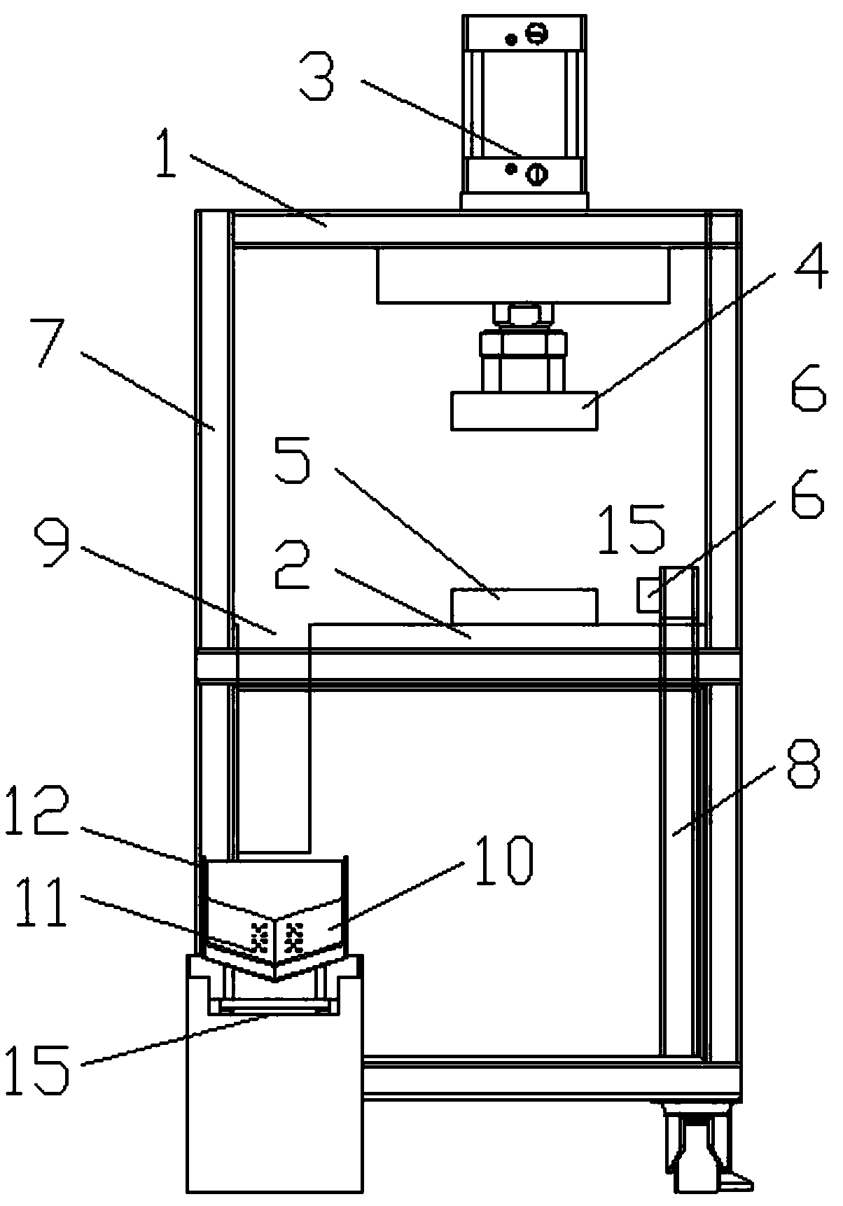
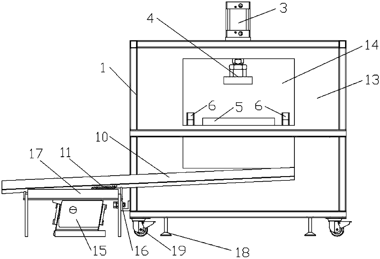
[0018] Such as figure 1 As shown, a waste material separation punching machine, a waste material separation type punching machine, includes a frame 1, a drive mechanism 3 positioned above the frame 1 and a working platform 2 positioned below the frame 1, the drive mechanism 3 below Connect the upper mold base 4, the working platform 2 is provided with the lower mold base 5, the upper mold base 4 is opposite to the lower mold base 5, and the working platform 2 is away from the back plate 7 of the frame 1 One side of the air outlet 6 is provided, and the air outlet 6 communicates with the air column 8 below the inside of the frame 1. The air outlet 6 is located at the top of the air...


PUM


Abstract

The invention discloses a waste separation punching machine, which comprises a frame, a driving mechanism located above the frame and a working platform located below the frame. There is an air outlet on the side of the platform away from the backboard of the frame, and the air outlet is slightly higher than the working platform. The end of the working platform close to the backboard is provided with a blanking opening. The bottom plane is provided with a dust drop hole, the separation groove passes through the frame and is connected with a vibrator below, and the vibrator is set outside the frame, the vibration generated by the vibrator will not affect the work of the punching machine, and it can also remove dust and waste Separation, using the air outlet to clean the punching machine, not only easy to clean, but also to cool down the equipment and increase the service life of the equipment.

Description

technical field [0001] The invention relates to the technical field of punching machines, in particular to a waste separation type punching machine. Background technique [0002] Stamping machine tools are referred to as stamping machines, also known as presses, which are equipment used for pressure processing of materials. Its working principle is generally to drive the opening and closing of the upper mold and the lower mold by the machine tool under the action of stamping power, and then cut, punch, stretch and other raw materials between them to form stamping parts. According to the working principle of the press, it can be divided into mechanical press and hydraulic press. The mechanical press completes the stamping process through the motor-driven slider movement; the hydraulic press uses the hydraulic principle to drive the hydraulic steel to reciprocate to complete the stamping process. The mechanical press has fast reciprocating frequency, high speed and high effi...

Claims


Application Information

Patent Timeline
Patent Type & Authority Applications(China)
IPC IPC(8): B21D28/02B21D55/00B21D43/20B21D45/00B21D37/16
CPCB21D28/02B21D37/16B21D43/20B21D45/00B21D55/00
Inventor 付朝黄荣利郭宁州
Owner 苏州特精模具有限公司
Why Eureka
Try Eureka