Convenient-to-clamp winding machine for transformer skeleton

一种变压器骨架、绕线机的技术,应用在电感/变压器/磁铁制造、线圈制造、电气元件等方向,能够解决耗费人力劳作、分布不均、返工等问题,达到避免缠绕打结、确保效率、提高效率的效果

Active Publication Date: 2018-04-17
XUZHOU SANHE AUTOMATIC CONTROL EQUIP
View PDF6 Cites 4 Cited by
  • Summary
  • Abstract
  • Description
  • Claims
  • Application Information

AI Technical Summary

Problems solved by technology

[0006] Most of the existing winding equipment for transformer skeletons fix the transformer on the turntable, and the winding of the transformer is realized through the rotation of the turntable. When winding, it is necessary to stop the machine frequently to adjust the position of the winding, so that the copper wire is relatively uniform. Winding on the transformer skeleton, using this method for winding, consumes a lot of manpower, and at the same time the effect of winding is not very good, it is prone to uneven distribution and lead to rework, and copper wire winding may also occur The case of knotting

Method used


Image

  • Convenient-to-clamp winding machine for transformer skeleton
  • Convenient-to-clamp winding machine for transformer skeleton
  • Convenient-to-clamp winding machine for transformer skeleton

Examples


Embodiment Construction

[0038] In order to enable those skilled in the art to better understand the technical solution of the present invention, the present invention will be described in detail below in conjunction with the accompanying drawings. The description in this part is only exemplary and explanatory, and should not have any limiting effect on the protection scope of the present invention. .

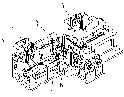
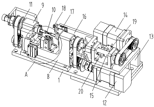
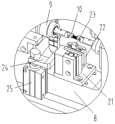
[0039] Such as Figure 1-Figure 8 As shown, the specific structure of the present invention is: a winding machine for a conveniently clamped transformer skeleton, which includes a support plate 1, and the support plate 1 is provided with a winding mechanism 3 and a wire releasing device 4 that cooperate with each other The winding mechanism 3 includes a winding seat 8 arranged on the support plate 1, and the winding seat 8 is provided with a winding shaft 11 whose two ends cooperate with each other, and the outer body of the winding shaft 11 is end is connected to the winding motor 12, the inner end o...


PUM


Abstract

The invention relates to a winding machine capable of accurately locating for a transformer skeleton. A support plate is provided with a winding mechanism and a pay-off device, wherein the winding mechanism comprises a winding seat arranged on the support plate; the winding seat is provided with a winding rotating shaft; an outer end of the winding rotating shaft is connected to a winding motor and an inner end is connected to a feed cylinder; the feed cylinder is provided with a clamping block matched with the transformer skeleton; the pay-off device comprises a pay-off seat; a pay-off plateand a wire outlet matched with a copper wire are arranged on the pay-off seat; the winding seat is provided with a connection block matched with the wire outlet; the connection block is matched with the height of the clamping block; and a connection port matched with the wire outlet is formed in the connection block. The winding rotating shaft is provided with the feed cylinder, the clamping blockmatched with the transformer skeleton is arranged on the cylinder head of the feed cylinder, and the vertical downward wire outlet is formed in a room device and matched with the connection block, sothat the copper wire can be uniformly wound on the transformer skeleton, and meanwhile, the copper wire is prevented from being entangled and knotted.

Description

[0001] Original application number: 2016112202910 [0002] Original application name: A winding machine for transformer skeleton [0003] The filing date of the original case: December 26, 2016. technical field [0004] The invention relates to the field of transformer processing equipment, in particular to a coil winding machine for a conveniently clamped transformer skeleton. Background technique [0005] With the acceleration of the electrification process, the application of various electrical components is becoming more and more widespread, and the transformer is one of them. Most of the transformers are composed of a transformer skeleton and a coil wound on it. In the process, it is necessary to carry out winding processing on the skeleton of the transformer. [0006] Most of the existing winding equipment for transformer skeletons fix the transformer on the turntable, and the winding of the transformer is realized through the rotation of the turntable. When windin...

Claims


Application Information

Patent Timeline
Patent Type & Authority Applications(China)
IPC IPC(8): H01F41/082H01F41/098H01F41/096H01F41/06
CPCH01F41/06H01F41/082H01F41/096H01F41/098
Inventor 邓君黄红梅邓凯
Owner XUZHOU SANHE AUTOMATIC CONTROL EQUIP
Why Eureka
Try Eureka