Injection molding method for mesh filter, injection molding mold, and mesh filter

An injection molding and filter technology, which is applied to membrane filters, chemical instruments and methods, fixed filter element filters, etc., can solve problems such as differences in filtration performance, increase in manufacturing man-hours, and uneven shapes and areas of openings 102. , to achieve the effect of improving durability, easy work control and reducing stress

Active Publication Date: 2018-04-17
ENPLAS CORP
View PDF5 Cites 0 Cited by
  • Summary
  • Abstract
  • Description
  • Claims
  • Application Information

AI Technical Summary

Problems solved by technology

[0006] However, Figure 10 The conventional mesh filter 100 shown in (a) to (d) is manufactured by insert molding, so it is necessary to accommodate the mesh member 103 in the cavity 110 compared to the case of integrally molding the whole by injection molding. The process of the specified position in the process, thus increasing the manufacturing man-hours accordingly (refer to Figure 10 (e))
and, Figure 10 (a) ~ (d) shown in the existing mesh filter 100 in the lattice shape of the nylon fiber 106 weaving tends to shift, the shape of the opening 102 and the area of ​​the opening 102 (the flow for the fluid to pass through). The cross-sectional area of ​​the passage) tends to be uneven, so there is a tendency to vary in the filtration performance (the ability to remove foreign matter larger than the specified particle size)

Method used


Image

  • Injection molding method for mesh filter, injection molding mold, and mesh filter
  • Injection molding method for mesh filter, injection molding mold, and mesh filter
  • Injection molding method for mesh filter, injection molding mold, and mesh filter

Examples


no. 1 approach

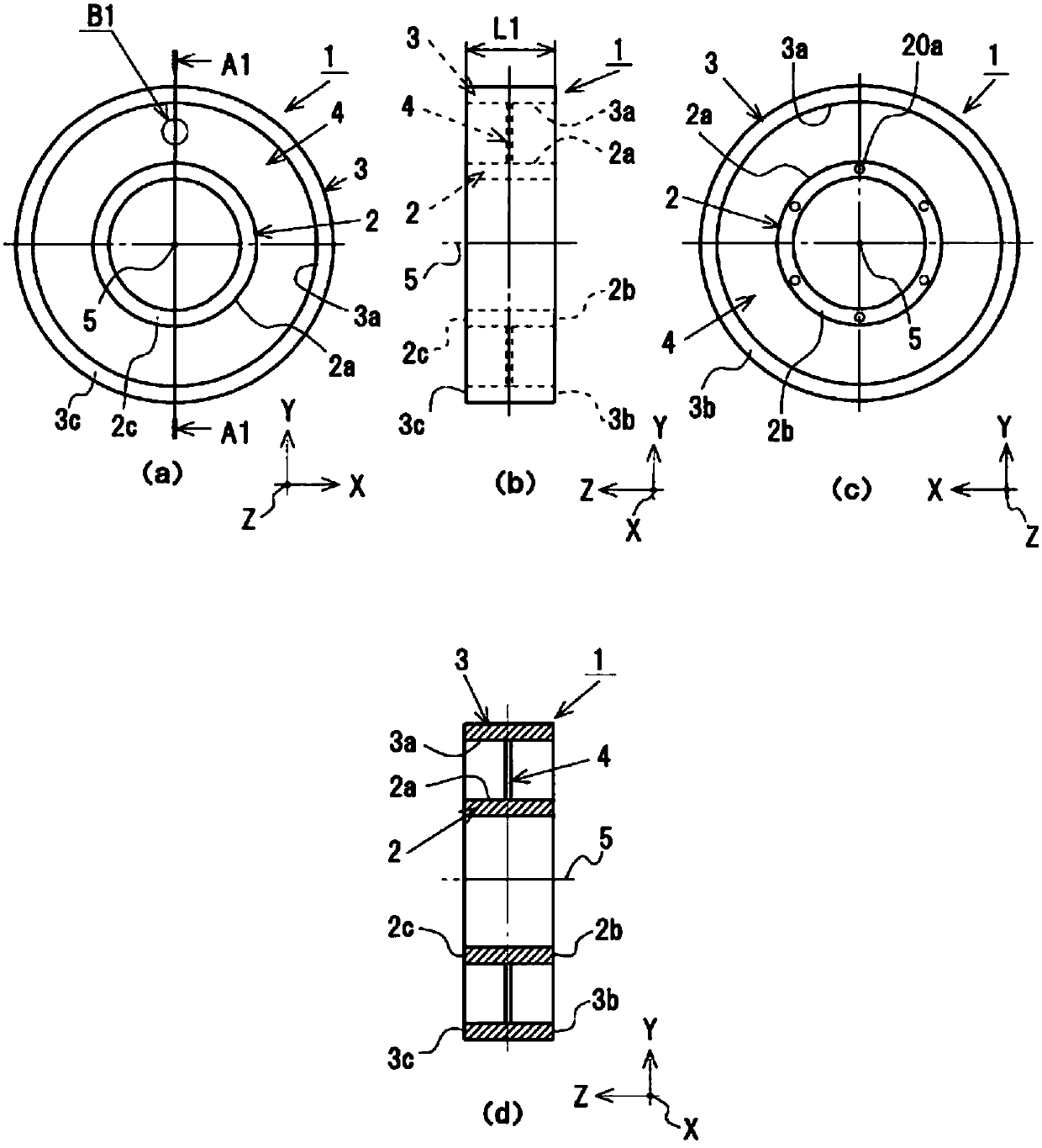
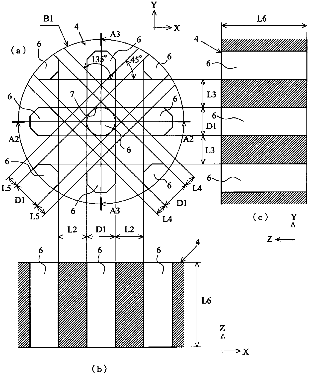
[0038] Figure 1 to Figure 2 It is a figure which shows the mesh filter 1 which concerns on 1st Embodiment of this invention. It should be noted, figure 1 (a) is a front view of the mesh filter 1, figure 1 (b) is a side view of the mesh filter 1, figure 1 (c) is a rear view of the mesh filter 1, figure 1 (d) is along figure 1 (a) is a cross-sectional view of the mesh filter 1 shown by the line A1-A1. also, figure 2 (a) is figure 1 Enlarged view of part B1 of (a) (partially enlarged view of mesh filter 1), figure 2 (b) is along figure 2 (a) A2-A2 line A2-A2 cross-sectional view (partial enlarged cross-sectional view of the screen filter 1), figure 2 (c) is along figure 2 (a) A3-A3 line cut-away cross-sectional view (partially enlarged cross-sectional view of the mesh filter 1).

[0039] As shown in these figures, the mesh filter 1 integrally has a cylindrical inner tube 2 (inner frame), and a cylindrical outer tube 3 (enclosed by an inner frame) concentric w...

no. 2 approach

[0060] Figure 6 It is a figure which shows the mesh filter 1 of 2nd Embodiment of this invention. to the Figure 6 In the shown mesh filter 1 of this embodiment, the same parts as those of the mesh filter 1 of the first embodiment are denoted by the same reference numerals, and descriptions that overlap with those of the mesh filter 1 of the first embodiment are omitted. . It should be noted, Figure 6 (a) is a front view of the mesh filter 1, Figure 6 (b) is a side view of the mesh filter 1, Figure 6 (c) is a rear view of the mesh filter 1, Figure 6 (d) is along Figure 6 (a) is a cross-sectional view of the mesh filter 1 shown by the line A6-A6.

[0061] The mesh filter 1 of the present embodiment has an inner filter portion 27 formed radially inside the inner cylinder 2 from the central axis 5 of the inner cylinder 2 to the inner peripheral surface 2 d of the inner cylinder 2 . The inner filter portion 27 is formed in the same manner as the filter portion 4 of t...


PUM


Abstract

To reduce mold releasing resistance between openings of mesh parts of a mesh filter serving as an injection molding article and opening forming pins of an injection molding mold to lessen a stress acting on the opening forming pins. A third cavity 17 forming a filter part of a mesh filter has opening forming pins 21 for forming a plurality of openings having a regular octagonal shape in the filterpart by the same number as that of the openings. The plurality of opening forming pins 21 is formed at even intervals along an X-axis direction and a Y-axis direction, and a diameter of inscribed circles 22 of the regular octagonal shapes is the same as a size between the opening forming pins 21 and 21 adjacent to each other along the X-axis direction and the Y-axis direction. An interval betweena first row of the plurality of opening forming pins 21 formed at even intervals along a direction of 45 degrees formed relative to the X-axis direction and a second row adjacent to the first row isthe same as an interval between a third row of the plurality of opening forming pins 21 formed at even intervals along a direction of 135 degrees formed relative to the X-axis direction and a fourth row adjacent to the third row.

Description

technical field [0001] The present invention relates to an injection molding method of a mesh filter used for filtering foreign matter in a fluid, an injection molding mold used for injection molding the mesh filter, and a mesh filter. Background technique [0002] For example, a mesh filter is arranged in the middle of a fuel supply pipe connected to a fuel injection device of an automobile, an oil pipe of a lubricating device, etc., and foreign substances in fluids such as fuel and oil are filtered by the mesh filter. [0003] Figure 10 It is a figure which shows the conventional mesh filter 100. It should be noted, Figure 10 (a) is the front view of existing mesh filter 100, Figure 10 (b) is a side view of an existing mesh filter 100, Figure 10 (c) is along Figure 10 (a) The cross-sectional view of the screen filter 100 shown by A8-A8 line cutaway, Figure 10 (d) is Figure 10 Enlarged view of part B4 of (a). also, Figure 10 (e) is a sectional view of the mold 101 ...

Claims


Application Information

Patent Timeline
Patent Type & Authority Applications(China)
IPC IPC(8): B29C45/37B29C33/44
CPCB29C33/44B29L2031/737B29C45/0046B01D2239/10B01D39/1692B29C45/2628B29L2031/14B29C45/37B01D29/0093B01D29/39B01D39/16B01D2201/0415B29C45/40
Inventor 中原道
Owner ENPLAS CORP
Why Eureka
Try Eureka