Relay device, control method of relay device, and readable recording medium

A technology of transfer device and control method, which is applied in the direction of program control, computer control, general control system, etc., and can solve complicated problems such as processing

Active Publication Date: 2021-08-03
ORMON CORP
View PDF7 Cites 0 Cited by
  • Summary
  • Abstract
  • Description
  • Claims
  • Application Information

AI Technical Summary

Problems solved by technology

[0010] In the prior art described above, in order to backup an IO-Link element, a backup instruction for the IO-Link element is required, but there is a problem that when there are many IO-Link elements to be backed up, the processing becomes complicated

Method used


Image

  • Relay device, control method of relay device, and readable recording medium
  • Relay device, control method of relay device, and readable recording medium
  • Relay device, control method of relay device, and readable recording medium

Examples


Embodiment approach 1

[0050] according to Figure 1 to Figure 4 Embodiment 1 of the present invention will be described.

[0051] [System Outline]

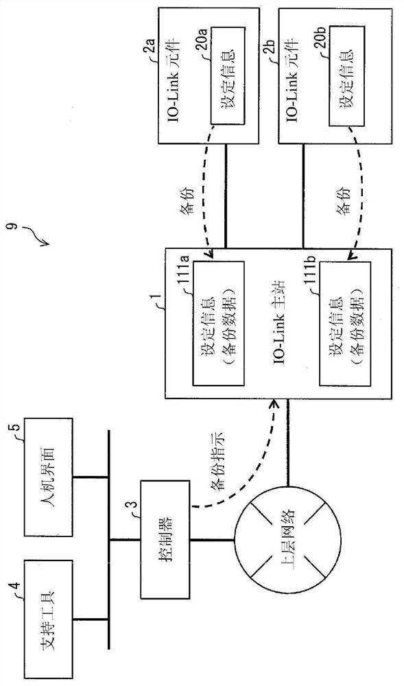
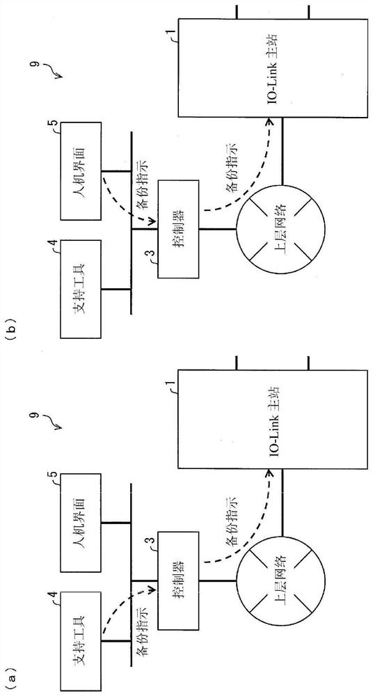
[0052] First, according to figure 2 The outline of the IO-Link system of this embodiment will be described. figure 2 It is a figure which shows the outline|summary of the IO-Link system 9. The IO-Link system 9 is an FA system. As shown in the figure, the IO-Link system 9 includes an IO-Link master station (relay device) 1, an IO-Link component 2a, an IO-Link component 2b, a controller (control device) ) 3, supporting tools 4, and human machine interface (Human Machine Interface, HMI) 5. In addition, when it is not necessary to distinguish between the IO-Link element 2a and the IO-Link element 2b, they are expressed as the IO-Link element 2 .

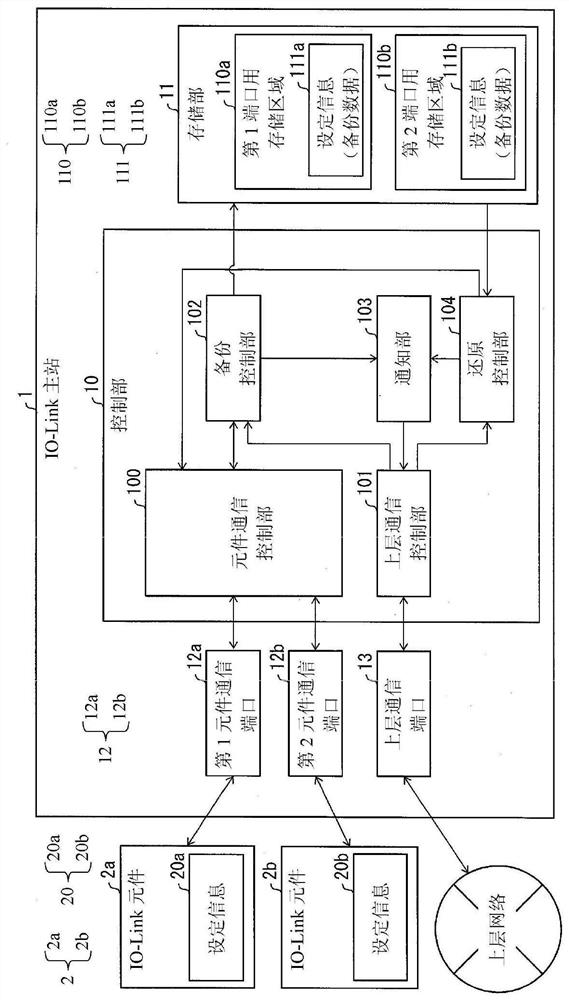
[0053] The IO-Link master 1 is a relay device that transfers data between an upper layer network including the controller 3 and the IO-Link device 2 , and operates as a slave device of the controller 3 in ...

Embodiment approach 2

[0091] according to Figure 5 Embodiment 2 of the present invention will be described, Figure 5 It is a diagram showing an example of the IO-Link master 1 that restores a plurality of IO-Link devices 2 in response to one restoration instruction. In addition, the same reference number is attached|subjected to the same structure as the said embodiment, and description is abbreviate|omitted. The same applies to the third and subsequent embodiments.

[0092] As shown in the figure, the IO-Link master station 1 of this embodiment sends setting information 111 to each of a plurality of IO-Link devices 2 in response to receiving a restoration instruction from the controller 3, so that each IO-Link The setting information 20 of Link device 2 is restored. More specifically, the restoration control unit 104 of the IO-Link master 1 transmits the setting information 111a to the IO-Link device 2a to be stored as the setting information 20a. Similarly, the restoration control unit 104 ...

Embodiment approach 3

[0097] according to Figure 6 Embodiment 3 of the present invention will be described. Figure 6 It is a diagram showing an example of the IO-Link system 92 in which the communication function with the upper layer network in the IO-Link master is separated into a communication coupler.

[0098] The illustrated IO-Link system 92 is a system having the same functions as the above-mentioned IO-Link system 9, but the IO-Link master station of the IO-Link system 9 is replaced by a communication coupler 200 and an IO-Link master station 201. Station 1 is different on this point.

[0099] The communication coupler 200 is a relay device that relays communication between the upper layer network and the IO-Link master 201 . The communication coupler 200 is equipped with the upper communication port 13 corresponding to the IO-Link master station 1 (refer to figure 1 ) communication port, and has a communication port for communicating with the IO-Link master station 201. Furthermore,...


PUM


Abstract

As the number of components to be backed up or restored increases, the number of commands to be sent increases, resulting in complicated processing. The present invention proposes a relay device, a control method of the relay device, and a readable recording medium, and realizes a relay device that can simply back up or restore setting information of multiple components. In the embodiment of the present invention, the IO-Link master station (1) has: an upper layer communication control unit (101), which receives setting information (20) obtained from the IO-Link component (2) and stores it in the storage unit (11 ) in order to execute the backup; and the backup control unit (102) executes the backup of a plurality of IO-Link devices (2) corresponding to the received one instruction.

Description

technical field [0001] The present invention relates to a transfer device for transferring data between a control device and components in a factory automation (FA) system. backup) function of the relay device, the control method of the relay device, and the readable recording medium, etc. Background technique [0002] A general FA system includes components such as a master device (control device), a slave device (relay device), and sensors. The master device controls the operation of the device or receives output data from the device through the slave device. Improvement of such FA systems has been carried out conventionally. For example, the following technology is disclosed in the following patent document 1: reducing the parameters of the control device (corresponding to the slave device) in a programmable logic controller (Programmable Logic Controller, PLC, corresponding to the master device) A technique to set the data communication volume when performing backup. ...

Claims


Application Information

Patent Timeline
Patent Type & Authority Patents(China)
IPC IPC(8): G05B19/042
CPCG05B19/042G05B2219/25242G05B2219/31333G05B19/052G05B19/054G05B19/4185G05B2219/23067G05B2219/23193
Inventor 北村安宏尾崎敏之上野真太郎
Owner ORMON CORP
Why Eureka
Try Eureka