Air purifying equipment for manufacturing

A kind of air purification equipment and technology of purification equipment, applied in chemical instruments and methods, separation of dispersed particles, filtration of dispersed particles, etc., can solve problems such as increasing the labor intensity of installers, damaging the physical and mental health of staff, and bulky air purification equipment. Achieve the effects of small footprint, convenient maintenance and replacement of purification filter elements, and simple structure

Inactive Publication Date: 2018-04-20
DONGGUAN ZHIPEI ELECTROMECHANICAL TECH CO LTD
View PDF0 Cites 0 Cited by
  • Summary
  • Abstract
  • Description
  • Claims
  • Application Information

AI Technical Summary

Problems solved by technology

[0003] The air purification equipment of the prior art has the following problems: 1. The use of various machines in the manufacturing process will have a certain discontinuity, that is, some places need to be purified, and some places do not need to be purified, but the existing manufacturing air Most of the purification equipment is bulky and inconvenient to carry. In order to avoid air pollution from damaging the physical and mental health of the staff, manufacturers have added air purification equipment in the air purification area, which not only increases the labor intensity of the installers, but also increases the purification of the enterprise. Cost; 2. At present, the filter element of air purification equipment has a limited service life and needs to be replaced from time to time to ensure the performance of the air purification equipment. However, most of the existing air purification equipment and filter elements are designed as an integrated structure. a lot of wasted resources

Method used


Image

  • Air purifying equipment for manufacturing
  • Air purifying equipment for manufacturing
  • Air purifying equipment for manufacturing

Examples


Embodiment Construction

[0019] The following will clearly and completely describe the technical solutions in the embodiments of the present invention with reference to the accompanying drawings in the embodiments of the present invention. Obviously, the described embodiments are only some, not all, embodiments of the present invention. Based on the embodiments of the present invention, all other embodiments obtained by persons of ordinary skill in the art without making creative efforts belong to the protection scope of the present invention.

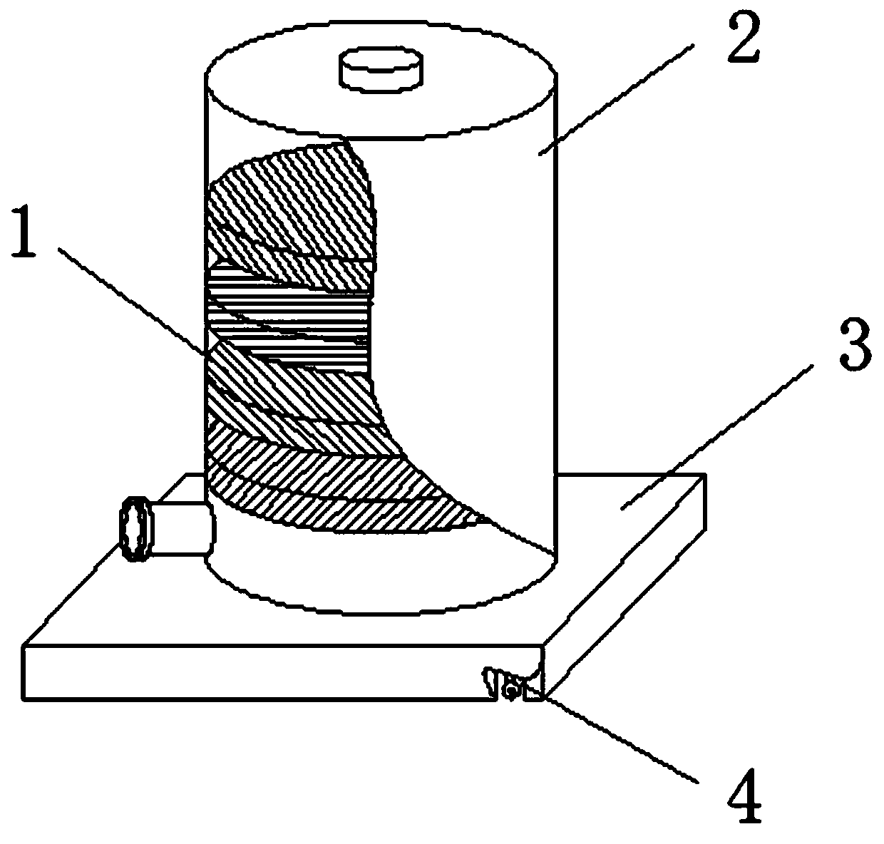
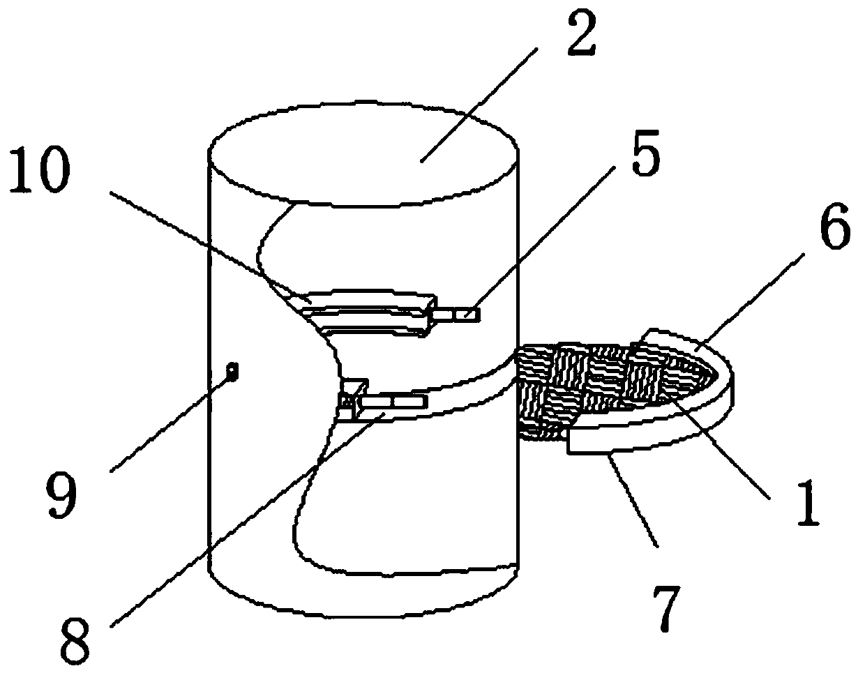
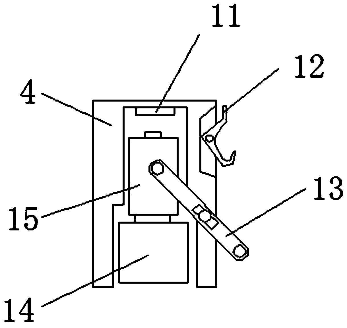
[0020] see Figure 1-4 , the present invention provides the following technical solutions: an air purification device for manufacturing, including a base plate 3, a telescopic chamber 4 and a fixing device 7, the four corners of the base plate 3 are provided with a telescopic chamber 4, and the top of the base plate 3 is provided with a purification equipment main body 2. An air outlet is provided above the main body 2 of the purification equipment. In order t...


PUM


Abstract

The invention discloses an air purification equipment for manufacturing, which comprises a bottom plate, a telescopic chamber and a fixing device. The four corners of the bottom plate are provided with telescopic chambers, and a main body of the purification equipment is provided above the bottom plate. The inner top of the telescopic chamber A fixed seat is provided, and a telescopic column is arranged under the fixed seat, and a rotating shaft is arranged at the middle position of the telescopic column, and a universal wheel is provided on the side of the telescopic column far away from the fixed seat, and the rotating shaft is far away from the side of the telescopic column. There is a hook on one side. The invention realizes the movable function of the universal wheel through the structure of the telescopic column, the rotating shaft and the hook; realizes the hidden function of the universal wheel through the magnet connected with the fixed column and the telescopic column; it is convenient for the removal of the purification equipment and at the same time can ensure the stability of the purification equipment It can purify multiple workshops with different purification times, which saves the cost of enterprise equipment equipment; it has high integration and small footprint, which is convenient for installation personnel to install.

Description

technical field [0001] The invention belongs to the technical field of air purification equipment, and in particular relates to an air purification equipment for manufacturing. Background technique [0002] The operation of various machines in the manufacturing process will cause the air in the factory to contain a large number of particles, bacteria, viruses and other harmful substances, which will damage the health of workers over time, especially for those who have been in the factory environment for a long time. With the improvement of the level, the requirements and expectations of workers for the quality of the indoor environment in their daily work are also constantly improving. The air purification technology in the factory building has become a new topic in the environmental field. More and more manufacturers are competing to produce air purification equipment for factories. , Where there is competition, there will be improvement. The production technology of the ex...

Claims


Application Information

Patent Timeline
Patent Type & Authority Applications(China)
IPC IPC(8): B01D46/12B01D46/00
CPCB01D46/0006B01D46/0008B01D46/12
Inventor 朱才兵
Owner DONGGUAN ZHIPEI ELECTROMECHANICAL TECH CO LTD
Why Eureka
Try Eureka