
A kind of dipping equipment and method thereof

A technology of dipping and equipment, which is applied in the field of rubber felt, can solve the problems of complex operation, high equipment investment, and large floor area, and achieve the effects of less equipment investment, flexible production, and small floor area

Active Publication Date: 2018-12-11
BEIJING AEROSPACE GEOTECHN ENG INST
View PDF4 Cites 0 Cited by
  • Summary
  • Abstract
  • Description
  • Claims
  • Application Information

AI Technical Summary

Problems solved by technology

[0005] The purpose of the present invention is to provide a dipping equipment and its method to solve the technical problems in the prior art such as large floor area, high equipment investment and complex operation.

Method used


Image

  • A kind of dipping equipment and method thereof
  • A kind of dipping equipment and method thereof
  • A kind of dipping equipment and method thereof

Examples


Embodiment 1

[0092] A kind of dipping method that present embodiment provides, it comprises the steps:

[0093] In step S1, the glass fiber mat is arranged in a roll shape;

[0094] Step S2, using high pressure to force the glue solution to flow through the glass fiber felt along the radial direction of the glass fiber felt roll.

[0095] In the above embodiment, more preferably, the glass fiber mat reel is placed horizontally, and the pressure value of the glue solution decreases gradually in the axial direction of the reel and in the direction extending from the middle of the reel to both ends thereof.

[0096] Specifically, in the radial direction of the glass fiber mat reel, the glue solution flows from the inside of the reel to the outside thereof, or the glue solution flows from the outside of the reel to the inside thereof. In the axial direction of the reel, the pressure value of the glue is normally distributed. When dipping, alternately input the glue solution from both ends of...

Embodiment 2

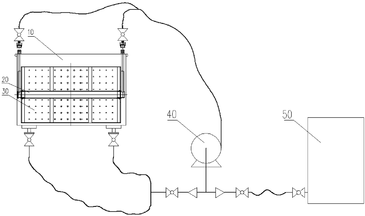
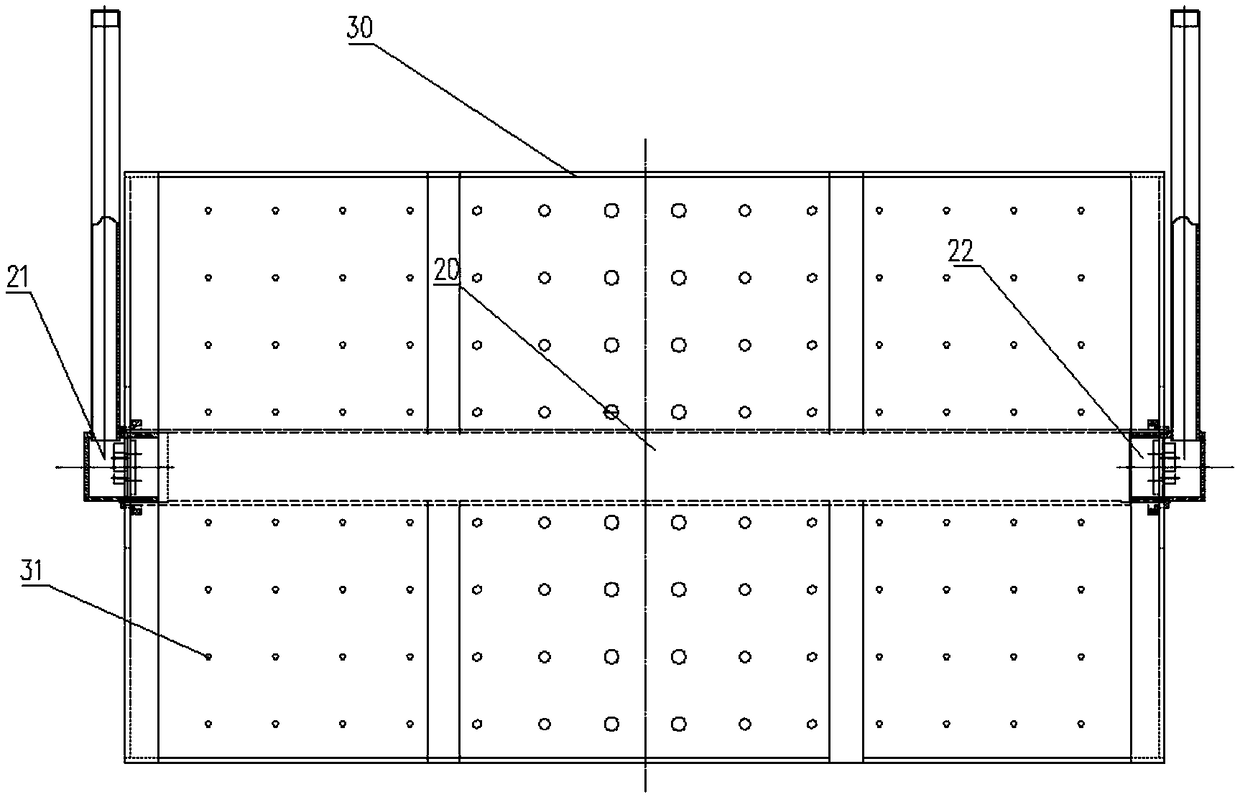
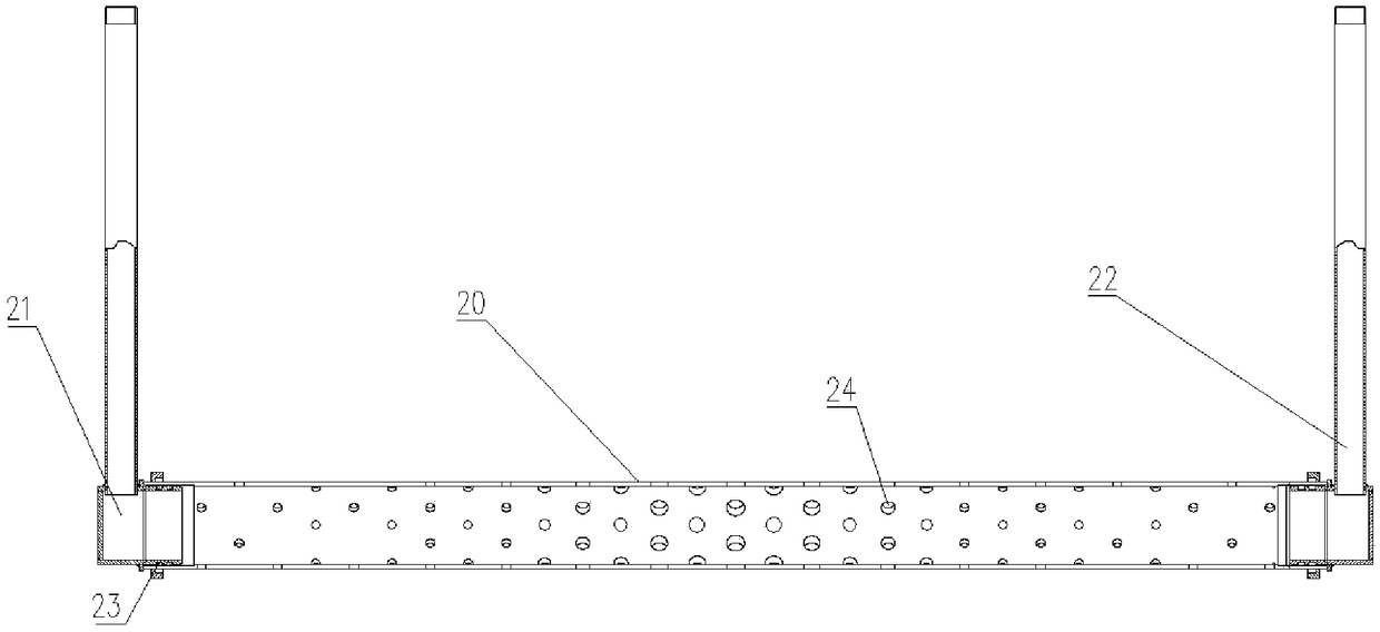
[0101] Such as Figure 1-7 As shown, this embodiment discloses a dipping equipment, which includes: a rubber injection sleeve 20, a pressure barrel 30 and a pump body 40;

[0102] The pressure-bearing barrel 30 is set outside the injection sleeve 20, and an annular cavity for accommodating the glass fiber felt reel is arranged between the two;

[0103] Such as image 3 As shown, the outer circular side of the injection sleeve 20 is provided with an injection hole 24 communicating with the inner and outer sides of the injection sleeve 20;

[0104] Such as figure 2 As shown, the outer circular side of the pressure barrel 30 is provided with a glue discharge hole 31 communicating with the inside and outside of the annular cavity;

[0105] The glass fiber felt is wound on the injection sleeve 20 to form a glass fiber felt roll;

[0106] The pump body 40 communicates with the cylinder cavity of the glue injection sleeve 20 through a pipeline, and is used to inject glue into th...


PUM


Abstract

The invention provides a rubber dipping device and a method thereof. The rubber dipping device includes a rubber injection sleeve, a pressure-bearing barrel and a pump body; the pressure-bearing barrel is set outside the rubber injection sleeve, and the rubber injection sleeve There is a glue injection hole connecting the inside and outside of the glue injection sleeve; the outer circular side of the pressure barrel is provided with a glue discharge hole that connects the inside and outside of the annular cavity; the glass fiber felt is wound on the glue injection sleeve to form a The glass fiber felt reel; the pump body communicates with the cavity of the injection sleeve through a pipeline, and is used to inject glue into the cavity, and use pressure to force the glue to pass through the injection sleeve in turn. The glue hole, the annular cavity and the glue discharge hole realize the dipping treatment of the glass fiber felt in the annular cavity. The invention can be produced in whole rolls, the length of the product is not limited by the length of the dipping equipment, and the air bubbles in the glass fiber mat can be quickly discharged, so that the glue is evenly impregnated into the glass fiber mat, and the production efficiency is increased by 30%.

Description

technical field [0001] The invention relates to the technical field of rubber mats, in particular to a dipping equipment and method for dipping glass fiber mats. Background technique [0002] Airgel felt is made of silica airgel as the main raw material, which is mixed with ordinary glass fiber. This product improves the 400°C high temperature resistance limit of ordinary glass fiber, and its thermal insulation performance is 3 to 8 times that of traditional materials. It can withstand high temperatures above 700°C and is flat, mechanically resistant, and easy to process. Its thermal conductivity is extremely low. It is a new type of material in the field of industrial thermal insulation applications. [0003] The existing dipping method is mainly to unfold the glass fiber felt roll and lay it flat in the cuboid gel tank as equipment for horizontal gel dipping. The size of the gel tank is 15m*2m*0.65m, which can hold 15m 3 Liquid, the glass fiber mat roll is spread flat in...

Claims


Application Information

Patent Timeline
Patent Type & Authority Patents(China)
IPC IPC(8): B05C3/04B05C3/12B05D1/18
CPCB05C3/04B05C3/125B05D1/18
Inventor 赵卓然乔倩梁鹏王剑锋孙文丹刘志军王福胜张茹胡冰
Owner BEIJING AEROSPACE GEOTECHN ENG INST
Learn More