Rotating shaft structure applied to glass turnover device and glass turnover device

A technology of turning device and rotating shaft structure, which is applied in the direction of transportation and packaging, conveyor objects, furnaces, etc. It can solve the problems of weakening of the supporting force of the rotating shaft, shaking of the rotating arm, and affecting the stability of the rotating arm of the turning device, so as to reduce the amount of shaking Effect

Pending Publication Date: 2018-04-20
昆山文特自动化设备有限公司
View PDF7 Cites 0 Cited by
  • Summary
  • Abstract
  • Description
  • Claims
  • Application Information

AI Technical Summary

Problems solved by technology

[0003] However, the subsequent problem of opening a through hole on the rotating shaft is that the supporting force of the rotating shaft is weakened, which in turn affects the stability of the rotating arm of the turning device after grabbing materials. For example, the rotating arm is prone to shaking after grabbing glass. time will affect the function of the turning device

Method used


Image

  • Rotating shaft structure applied to glass turnover device and glass turnover device
  • Rotating shaft structure applied to glass turnover device and glass turnover device
  • Rotating shaft structure applied to glass turnover device and glass turnover device

Examples


Embodiment 1 5

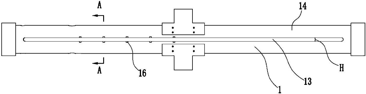
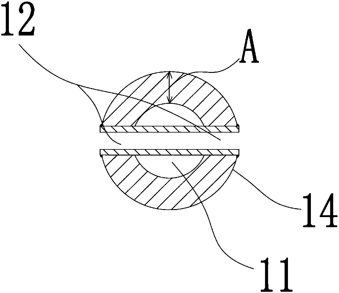
[0024] see Figure 1 to Figure 3 , the figure shows a rotating shaft structure applied to a glass flipping device provided by Embodiments 1 to 5 of the present invention, which includes a rotating shaft body 1 with a chamber 11 inside the rotating shaft body 1, and a through hole group is provided on the surface of the rotating shaft body 1 12 (multiple groups can also be set as required), the through hole group 12 includes two oppositely arranged through holes 13, the two through holes 13 are respectively located on the opposite side surfaces 14 of the rotating shaft body 1, and the through holes 13 are along the rotating shaft body 1 Axially extending strip holes.

[0025] Wherein, the height H of the through hole 13 and the wall thickness A of the shaft body 1 are respectively shown in the following table:

[0026]

[0027]

[0028] The above-mentioned measurement of the present invention can be completed by using an angle measuring instrument. Through the above-ment...

Embodiment 6

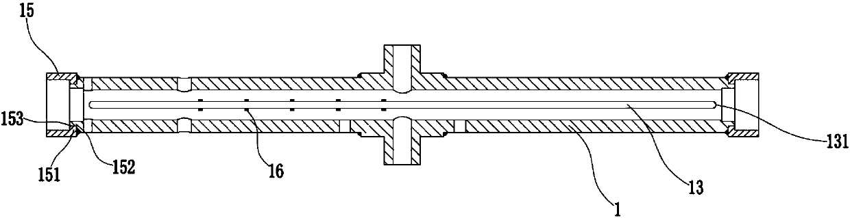
[0030] see Figure 1 to Figure 3 , the figure shows a rotating shaft structure applied to the glass turning device provided by Embodiment 6 of the present invention. On the basis of the above embodiments, this embodiment further makes the following technical solutions as improvements: through holes 13 Both ends 131 of the glass are arc-shaped ends, which can facilitate the formation of avoidance structures for glass ends.

Embodiment 7

[0032] see Figure 1 to Figure 3 , the figure shows a rotating shaft structure applied to the glass turning device provided by Embodiment 7 of the present invention. On the basis of the above embodiments, this embodiment further makes the following technical solutions as improvements: the rotating shaft body 1 A shaft sleeve 15 is set at opposite ends of the shaft sleeve 15, the inner wall of the shaft sleeve 15 has an axial convex edge 151, and the outer wall of the rotating shaft body 1 has a circumferential groove or a stepped surface 152 matching with the convex edge 151, and the convex edge 151 and The connection of the groove or the stepped surface 152 is welded by a V-shaped weld 153 . Through the setting of the above structure, the connection between the shaft sleeve and the rotating shaft body can be made more stable.


PUM


Abstract

The invention provides a rotating shaft structure applied to a glass turnover device and further provides the glass turnover device. The rotating shaft structure comprises a rotating shaft body. The rotating shaft body is internally provided with a cavity; at least one through hole set is formed in the surface of the rotating shaft body; each through hole set comprises two oppositely-formed through holes, wherein the two through holes are located in the surfaces of the two opposite sides of the rotating shaft body correspondingly; and the through holes are strip-shaped holes extending in the axial direction of the rotating shaft body, the height of each through hole is 8-16 mm, and the wall thickness of the rotating shaft body is 21-35 mm. Compared with the prior art, through the rotatingshaft structure applied to the glass turnover device, the requirement of turning-over of glass and the requirement of horizontal passing of the glass can be met simultaneously.

Description

technical field [0001] The invention relates to a rotating shaft, in particular to a rotating shaft structure applied to a glass turning device and the glass turning device. Background technique [0002] In the production of glass, especially in the production of automobile glass, in order to facilitate the processing of different surfaces of automobile glass, it is usually necessary to turn the glass over several times to meet the needs of production. The current overturning devices are usually installed on the glass conveyor line, and some overturning devices will avoid the position in the horizontal direction on the overturning device in order to meet the needs of horizontal conveying and overturning operations on the conveyor line at the same time. holes to allow glass to pass through horizontally. [0003] However, the subsequent problem of opening a through hole on the rotating shaft is that the supporting force of the rotating shaft is weakened, which in turn affects...

Claims


Application Information

Patent Timeline
Patent Type & Authority Applications(China)
IPC IPC(8): B65G49/06
CPCB65G49/063B65G2201/022
Inventor 杨柏杨
Owner 昆山文特自动化设备有限公司
Why Eureka
Try Eureka