Device and method for designing temporary drainage system used for debugging of process system in nuclear power plant

A process system and drainage system technology, which is applied in the field of temporary drainage system design device for nuclear power plant process system debugging, can solve the problems of multi-site construction space and drainage pipeline occupation, so as to improve the overall project efficiency, reduce occupation and avoid negative impact Effect

Active Publication Date: 2018-04-20
中广核工程有限公司 +1
View PDF7 Cites 0 Cited by
  • Summary
  • Abstract
  • Description
  • Claims
  • Application Information

AI Technical Summary

Problems solved by technology

At the same time, intensive design was carried out for the drainage requirements of multiple systems and regions during the entire commissioning period, the pipelines were simplified, and the problem of drainage pipelines occupying too much construction space on site was solved.

Method used


Image

  • Device and method for designing temporary drainage system used for debugging of process system in nuclear power plant
  • Device and method for designing temporary drainage system used for debugging of process system in nuclear power plant
  • Device and method for designing temporary drainage system used for debugging of process system in nuclear power plant

Examples


Embodiment 1

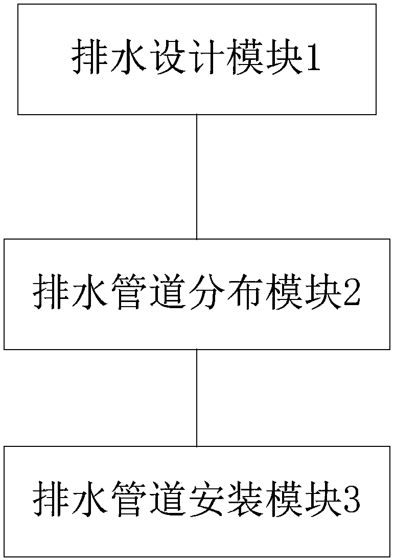
[0052] figure 1 It shows the temporary drainage system design device for the commissioning of the nuclear power plant process system in the present invention, which includes:

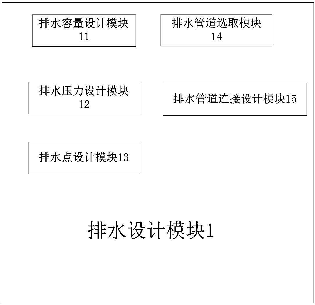
[0053] Drainage design module 1, which is used to design a temporary drainage system according to the debugging drainage requirements of the nuclear power plant process system; since the temporary drainage system belongs to the temporary system during the commissioning period and does not affect the functions during the normal operation of the power plant, the temporary drainage system is designed as Non-seismic, non-safety related systems;

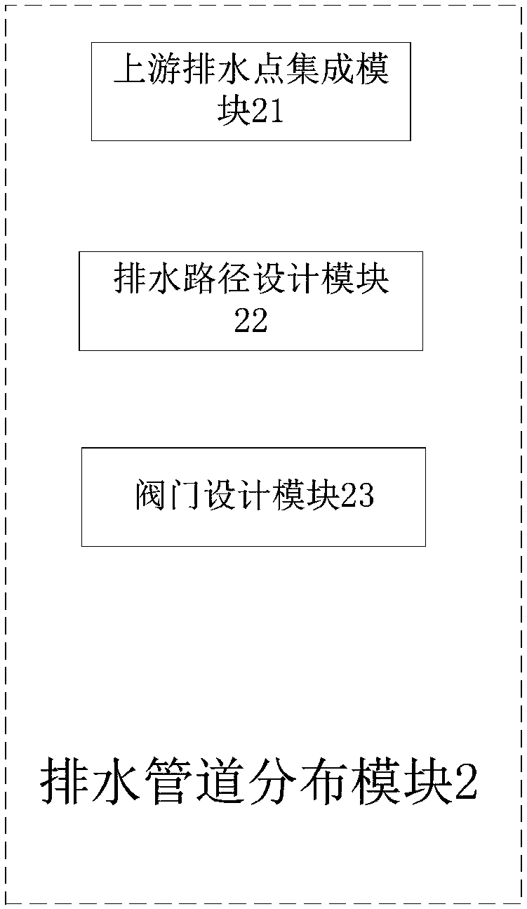
[0054] The drainage pipe distribution module 2, which is connected to the drainage design module 1, is used to generate the distribution status data of the drainage pipes according to the design data of the temporary drainage system;

[0055] The drainage pipe installation module 3 is connected to the drainage pipe distribution module 2, and is used for receiving ...

Embodiment 2

[0072] Such as Figure 5 As shown, the present invention also provides a temporary drainage design method for nuclear power plant process system debugging, which includes the following steps:

[0073] S1. Design temporary drainage system;

[0074] S2. Generate distribution state data of drainage pipes according to the design data of the temporary drainage system, and design a temporary drainage pipe system;

[0075] S3. Perform actual installation of the temporary piping system according to the temporary drainage piping system;

[0076] S4. Maintain and use the temporary drainage pipeline system;

[0077] S5. Dismantling the temporary drainage pipeline system.

[0078] Specifically, the step S1 includes:

[0079] S11. Design the drainage capacity according to the drainage requirements of the nuclear power plant process system commissioning;

[0080] S12. Determine the drainage pressure according to the pressure difference between the upstream process system and the downst...


PUM


Abstract

The invention discloses a device and method for designing a temporary drainage system used for debugging of a process system in a nuclear power plant. The device comprises a drainage designing module,a drainage pipeline distribution module and a drainage pipeline installation module. The drainage designing module is used for designing the temporary drainage system, the drainage pipeline distribution module is used for generating distribution state data of a drainage pipeline according to designing data of the temporary drainage system; the drainage pipeline installation module is used for receiving distribution state data of the drainage pipeline, and executing installation of the drainage pipeline according to the distribution state data of the drainage pipeline. With the device and method, the drainage system used for debugging of the process system in the nuclear power plant can be planned in advance and constructed in a concentrated mode, labor and material waste caused by randomlaying and repeated constructing is avoided, and waiting time for debugging work is shortened. Meanwhile, intensive design is performed for multi-system and multi-region drainage demands in the wholedebugging period, the pipeline is simplified, and the problem that the drainage pipeline occupies excessive on-site construction space is solved.

Description

technical field [0001] The invention relates to the commissioning work of nuclear power plants, in particular to a temporary drainage system design device and design method for process system commissioning of nuclear power plants. Background technique [0002] After the installation of each process system in a nuclear power plant is completed, functional tests of each system need to be carried out, and important tasks such as subsequent fuel loading and handover to power generation can only be carried out after each system has passed the commissioning. During the commissioning of each system, different systems and the same system will have drainage requirements at different locations at different stages, especially in flushing tests and functional verification tests. There will also be repeated and large-scale drainage requirements. [0003] The parallel construction of commissioning and installation is generally adopted in the construction of nuclear power plants, that is, ...

Claims


Application Information

Patent Timeline
Patent Type & Authority Applications(China)
IPC IPC(8): E03F1/00E03F3/02
CPCE03F1/00E03F3/02
Inventor 丁楠陈静
Owner 中广核工程有限公司
Why Eureka
Try Eureka