
Protecting device for wellhead of water injection well

A protection device and a technology for water injection wells, which are applied in the direction of wellbore/well valve devices, wellbore/well components, production fluids, etc., and can solve the problems of increased cost of measures, poor setting of packers, and inability of the center pipe to run in and other issues to achieve the effect of improving operation efficiency, avoiding complicated construction, and realizing safe injection

Active Publication Date: 2018-04-20
BC P INC CHINA NAT PETROLEUM CORP +1
View PDF5 Cites 2 Cited by
  • Summary
  • Abstract
  • Description
  • Claims
  • Application Information

AI Technical Summary

Problems solved by technology

Since water injection wells are mostly 250-type wellhead Christmas trees, and at the same time, the wellheads of water injection wells are under high-pressure production for a long time, wellhead punctures and leaks often occur during operation, and gates are not tightly sealed. Therefore, the wellheads of water wells need to be replaced before the transformation. Caused a growth in the measure cycle and an increase in the cost of the measure
[0003] The existing wellhead protection devices are mainly used for the protection of oil and gas well fracturing and acidizing operations or the simple protection of production wells, which cannot effectively solve the problem of serious fouling of the wellbore and the inner wall of the tubing after the long-term operation of the water injection well, the central pipe cannot be lowered, There are problems such as poor setting of the packer. At the same time, this type of protector does not involve related structures. During the process of pulling out the protector, it is ensured that no stuck pipe occurs, and there is a greater risk in field operations.

Method used


Image

  • Protecting device for wellhead of water injection well
  • Protecting device for wellhead of water injection well

Examples


Embodiment 1

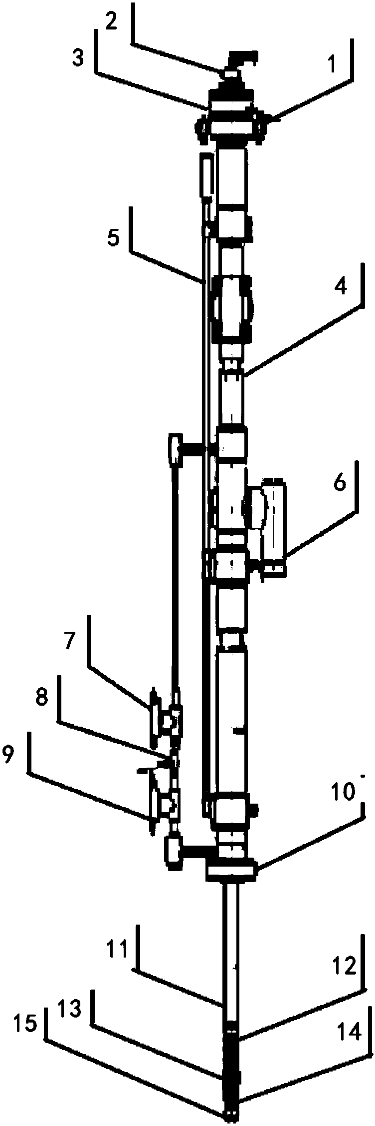
[0025] Such as figure 1 As shown, a wellhead protection device for a water injection well includes a leg fixing bracket 5, a hydraulic motor 3 and a hydraulic cylinder 4 fixedly mounted on the leg fixing bracket 5, a lifting ring 1 is installed on the upper part of the hydraulic motor 3, and the bottom of the hydraulic motor 3 The bottom end of the hydraulic cylinder 4 is connected to the top of the hydraulic cylinder 4, and the bottom end of the hydraulic cylinder 4 is connected with a slide pipe 11 through the wellhead connecting flange 10. The lower end of the slide pipe 11 is sequentially sleeved with a packer 12, a spring torque sleeve 13 and a well gauge 14. The bottom of the well gauge 14 is connected with an anti-loosening nut 15 by a shear pin.

[0026] Among them, the lifting ring 1 is mainly used for the installation and lifting of the sling of the wellhead protection device, and the leg fixing bracket 5 is used for installing the triangular fixed legs of the wellhe...

Embodiment 2

[0029] On the basis of Embodiment 1, the bottom of the well gauge is connected with an anti-loosening nut through a shear pin, and the anti-loosening nut is installed at the lowermost end of the protection device of the present invention, and is mainly used to prevent spring torque sleeves, packing At the same time, if there is resistance when pulling out the protector, increase the pulling force to shorten the pin of the anti-loosening nut, and keep the anti-loosening nut, packer, spring torque sleeve and other tools in the well. Ensure that the protective device can be lifted out normally, avoid complicated construction, and improve operation safety.

Embodiment 3

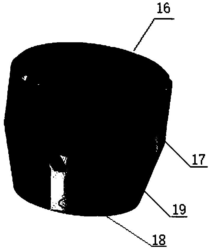
[0031] On the basis of the above-mentioned embodiments, the well gauge 14 is specially designed and processed according to the serious fouling of the tubing in the water injection well, such as figure 2 As shown, the well gauge 14 at least includes a main body 16, the main body 16 is provided with a guide flow hole 19, and the outer surface of the main body 16 is provided with a plurality of scraping teeth 17, and the plurality of scraping teeth 17 are along the circumferential direction of the main body 16. Evenly arranged, considering that the scraping teeth 17 have sufficient strength, the scraping teeth 17 can be manufactured integrally with the body 16 , and the bottom of the body 16 is provided with threaded pin holes 18 . The scraping teeth 17 can scrape the inner wall of the tubing and effectively remove the scaling on the inner wall of the tubing; the diversion holes 19 are used to guide sediment out of the well gauge body.

[0032] The scraping teeth 17 are arranged...


PUM


Abstract

The invention discloses a protecting device for a wellhead of a water injection well. The protecting device comprises a supporting foot fixing support, a hydraulic motor and a hydraulic oil cylinder,wherein the hydraulic motor and the hydraulic oil cylinder are fixedly installed on the supporting foot fixing support. A lifting ring is installed on the upper portion of the hydraulic motor; the bottom end of the hydraulic motor is connected with the top end of the hydraulic oil cylinder, and the bottom end of the hydraulic oil cylinder is connected with a sliding pipe through a wellhead connecting flange; the lower end of the sliding pipe is sleeved with a packer, a spring torque sleeve and a gauge cutter sequentially; and the bottom of the gauge cutter is connected with an anti-falling nutthrough a shearing pin. The protecting device is installed on the upper portion of the wellhead of the water injection well; the sliding pipe can be put downwards to the designated position below thewellhead, and setting of the packer is conducted so as to guarantee that liquid can be directly injected into the well without the need of passing through the wellhead; meanwhile, the wellhead protecting device can replace the wellhead to bear pressure, the wellhead pressure-bearing grade is improved, and the operation wellhead does not need to be replaced in the water injection well measure modifying process; and safe injection in water injection well measure operation is achieved, and the operation efficiency is improved.

Description

technical field [0001] The invention belongs to the technical field of water injection well operation equipment, and in particular relates to a water injection well head protection device. Background technique [0002] Advance water injection is one of the key technologies in the development of low-permeability reservoirs, and the injection rate of water injection wells is directly related to the production of oil wells. After long-term production, water injection wells will have different degrees of under-injection, and regular measures to reduce pressure and increase injection are required. Since water injection wells are mostly 250-type wellhead Christmas trees, and at the same time, the wellheads of water injection wells are under high-pressure production for a long time, wellhead punctures and leaks often occur during operation, and gates are not tightly sealed. Therefore, the wellheads of water wells need to be replaced before the transformation. Caused the growth of ...

Claims


Application Information

Patent Timeline
Patent Type & Authority Applications(China)
IPC IPC(8): E21B33/03E21B34/02E21B43/20
CPCE21B33/03E21B34/02E21B43/20Y02A20/00
Inventor 柴龙兰建平钟新荣白明伟王文渭付军刚寇泉侯光东李丹车昊阳杨敏叶赛牛亚红夏玉磊李花花
Owner BC P INC CHINA NAT PETROLEUM CORP
Learn More