
Clockwork self-deceleration valve protection device

A protection device and clockwork technology, applied in valve devices, devices to prevent accidental or unauthorized action, valve lifters, etc., can solve problems such as fluid leakage, valve internal structure impact, loss, etc., to achieve a soft braking effect , The effect of repeated use, saving and long service life

Active Publication Date: 2019-04-23
浙江祥和阀门有限公司
View PDF5 Cites 0 Cited by
  • Summary
  • Abstract
  • Description
  • Claims
  • Application Information

AI Technical Summary

Problems solved by technology

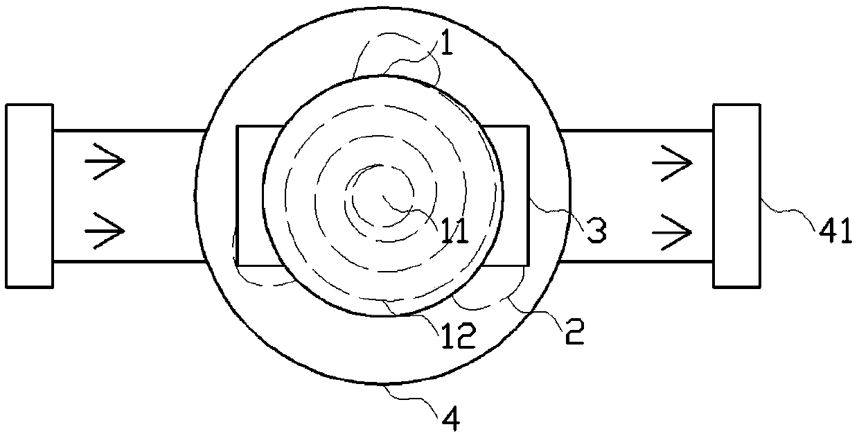
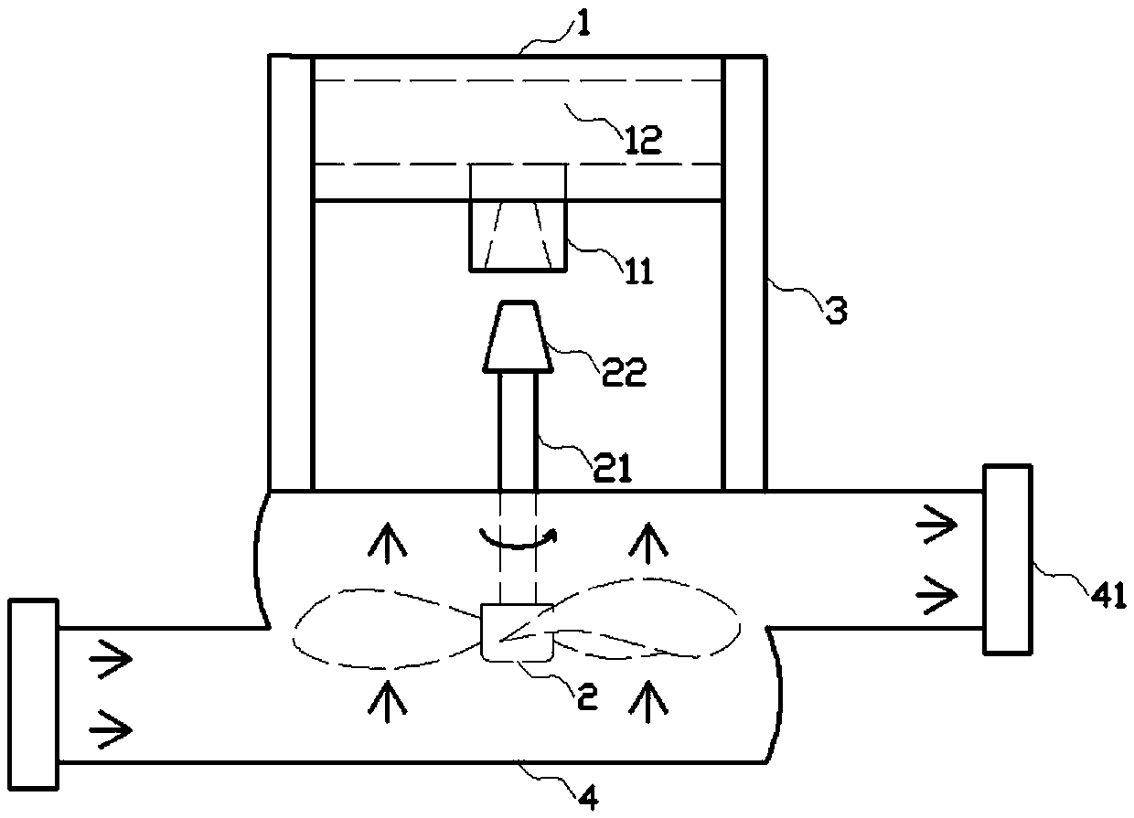
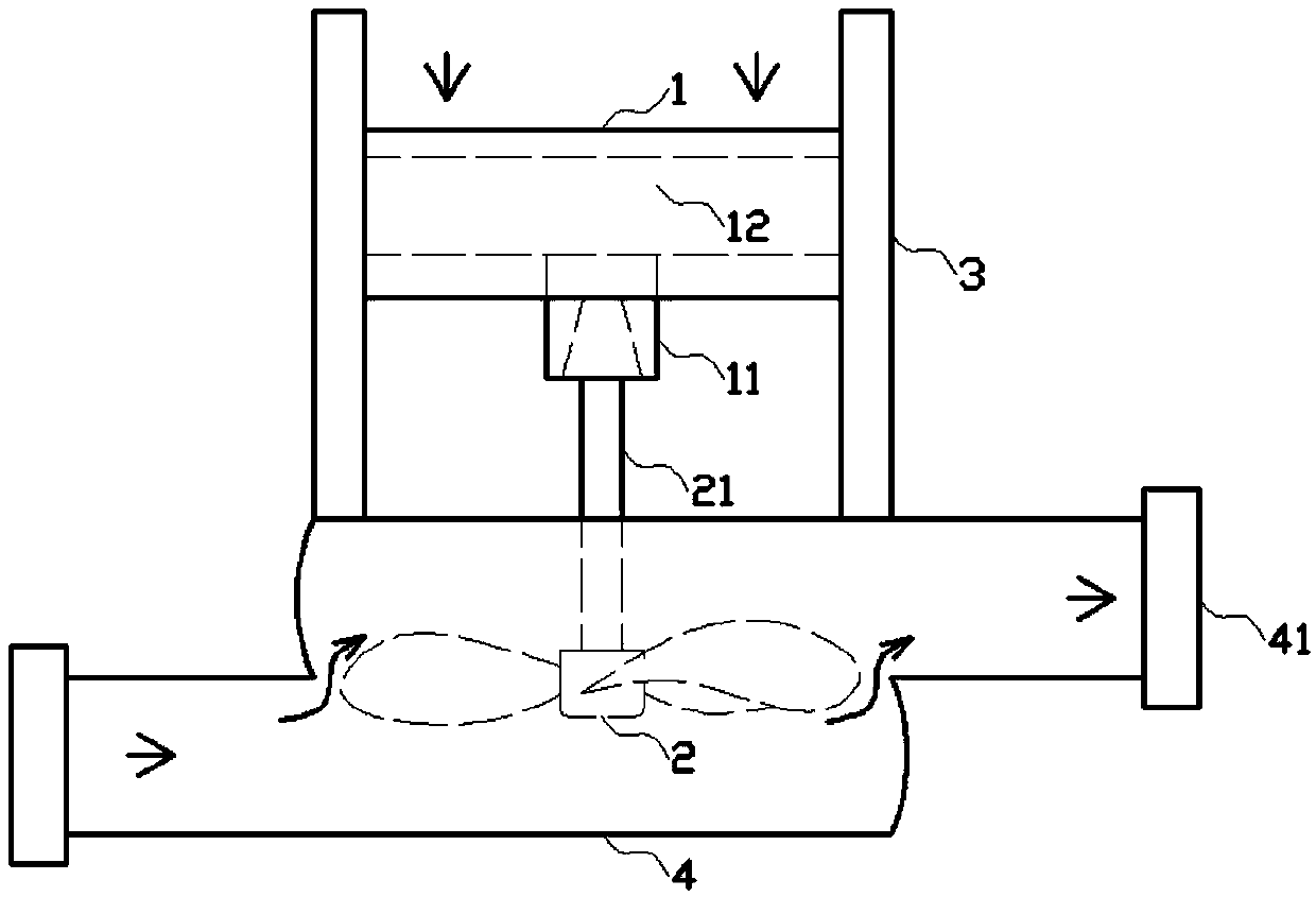
[0002] Valves are pipeline accessories used to open and close pipelines, control flow direction, adjust and control the parameters of the conveying medium; according to their functions, they can be divided into shut-off valves, check valves, regulating valves, etc.; The functions of flow, reverse flow prevention, pressure stabilization, diversion or overflow and pressure relief; the existing valves can realize the switch of fluid, including manual switch and automatic switch, and the valve with special requirements also has a timing function, which can realize timing switch, In order to realize the control of fluid flow; the existing valve device needs to apply force to the valve stem in the process of opening and closing to control the opening and closing of the internal structure of the valve; When the internal fluid pressure is too high, the user needs to apply a large control force to operate the valve, so it is difficult for the user to operate, and it will also delay the best time for the valve to open and close, resulting in a decline in the use effect; in addition, When the user operates the valve, the internal structure of the valve will be impacted due to the interaction between the fluid force inside the valve connecting pipe and the force exerted by the user on the valve. If the impact force is too large, it will damage the valve. The internal parts of the valve are damaged, so that the valve is damaged, not only cannot control the pipeline fluid, but also requires manual maintenance due to fluid leakage, resulting in unnecessary losses; in summary, there are defects

Method used


Image

  • Clockwork self-deceleration valve protection device
  • Clockwork self-deceleration valve protection device
  • Clockwork self-deceleration valve protection device

Examples


Embodiment Construction

[0013] Below in conjunction with accompanying drawing and embodiment the present invention is further described:

[0014] Such as figure 1 , figure 2 , image 3 As shown in the embodiment, the spring-type self-decelerating valve protection device is a kind of device that can reduce the flow velocity of the fluid inside the pipeline, thereby reducing the force required for the opening and closing of the valve; It is a device that absorbs the force and thus has the effect of buffering and protecting the device. It includes a clockwork module 1, a fan blade module 2, a sliding track plate 3 and a pipeline module 4; the clockwork module 1 includes a casing, a clockwork 12, a rotating shaft 11; the two ends of the housing are designed with bar-shaped protrusions, and the bottom of the housing is designed with a rotating hole; the clockwork 12 is installed inside the housing, and the center of the clockwork 12 is installed on the rotating Above the hole, the outer ring end of th...


PUM


Abstract

The invention provides a spring type self-decelerating valve protecting device. The device comprises a spring module, a blade module, a sliding rail plate and a pipeline module; the spring module comprises a casing, a spring and a rotating shaft; the blade module comprises a connecting rod and an impeller; strip-shaped grooves are formed in the sliding rail plate; a round cake-shaped pipeline is designed on the pipeline module and includes an upper layer and a lower layer; and pipeline openings are designed in the upper layer and the lower layer of the round cake-shaped pipeline respectively.By the aid of the device, the flow speed of a fluid inside the pipeline can be reduced, so that the stress required during opening and closing of a valve is reduced; and meanwhile, the acting force isabsorbed by the aid of the elastic structure of the spring device, so that the buffer protection effect is realized for the device.

Description

technical field [0001] The invention relates to the field of valves, in particular to an automatic protection valve device. Background technique [0002] Valves are pipeline accessories used to open and close pipelines, control flow direction, adjust and control the parameters of the conveying medium; according to their functions, they can be divided into shut-off valves, check valves, regulating valves, etc.; Flow, anti-backflow, voltage stabilization, diversion or overflow pressure relief and other functions; the existing valves can realize the switch of fluid, including manual switch and automatic switch, and the valve with special requirements also has a timing function, which can realize timing switch, In order to realize the control of fluid flow; the existing valve device needs to apply force to the valve stem in the process of opening and closing to control the opening and closing of the internal structure of the valve; for the valve body with butterfly valve structu...

Claims


Application Information

Patent Timeline
IPC IPC(8): F16K1/22F16K1/48F16K1/50F16K37/00F16K35/00
CPCF16K1/221F16K1/482F16K1/50F16K35/00F16K37/0091
Inventor 解钟敏刘鲲鹏
Owner 浙江祥和阀门有限公司
Learn More