
Control system and method for intelligent office lock

A technology of a control system and a control method, applied in the application field of smart locks, can solve the problems of inability to open the smart lock, easily damaged parts, unstable performance, etc.

Active Publication Date: 2018-04-20
深圳安时达技术服务有限公司
View PDF7 Cites 6 Cited by
  • Summary
  • Abstract
  • Description
  • Claims
  • Application Information

AI Technical Summary

Problems solved by technology

[0003] In the existing technology, from the point of view of the smart lock itself, its performance is still sometimes unstable. When encountering external harsh environments (such as encountering high temperature, strong magnetic shock, etc.), some smart locks may fail phenomenon; or when used for a long time, some parts are easily damaged (such as the fingerprint reader), and the user cannot open the smart lock from the only authority

Method used


Image

  • Control system and method for intelligent office lock
  • Control system and method for intelligent office lock

Examples


Embodiment 1

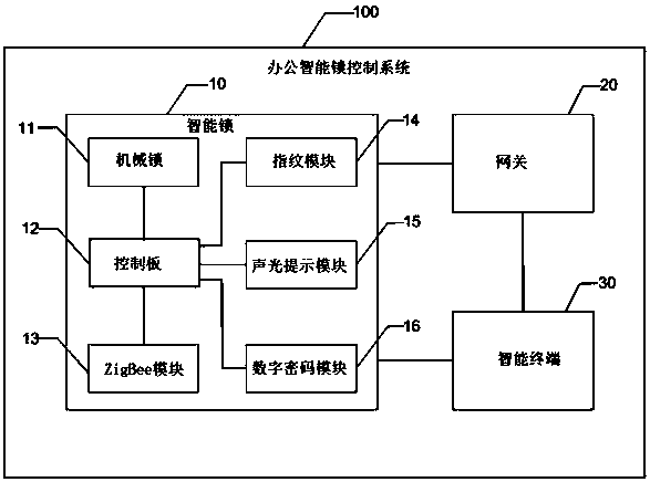
[0038] figure 1 It is a structural schematic diagram of an office intelligent lock control system of the present invention. The office intelligent lock control system 100 includes an intelligent lock 10, a gateway 20 and an intelligent terminal 30 connected by mutual communication, wherein:

[0039] The gateway 20 is configured to forward the first control instruction or the first monitoring instruction of the smart terminal 30 to the smart lock 10; preferably, the gateway 20 adopts ZigBee (short-distance, low-power wireless communication technology ) networking mode, through ZigBee modules of multiple smart locks 10, based on 3G / 4G or WIFI network, upload data to the smart terminal, monitor and manage through the smart terminal; the ZigBee module can match multiple (1-3 handle) the smart lock 10, and can manage the smart lock 10, and can also manage and control the smart lock 10 separately; through the gateway 20, the remote control of the smart lock 10 can be realized, and t...

Embodiment 2

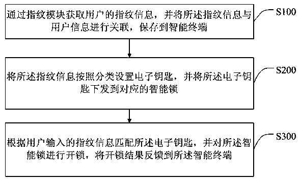
[0061] figure 2 It is a flow chart of the first preferred embodiment of the control method of the office intelligent lock control system of the present invention. As shown in the figure, it is a control method of the office intelligent lock control system. The control method includes:

[0062] Step S100, acquire the fingerprint information of the user through the fingerprint module, associate the fingerprint information with the user information, and save it in the smart terminal.

[0063] In the embodiment of the present invention, the fingerprint information of the user is entered in advance through the fingerprint identification module on the smart lock, and the main unlocking fingerprint and the backup unlocking fingerprint are set, and the fingerprint information is entered from multiple directions, and then the fingerprint information is compared with the user information. Associated storage, stored in the management file of the smart terminal, the manager can add, dele...


PUM


Abstract

The invention discloses a control system and method for an intelligent office lock. The control system for the intelligent office lock comprises a gateway, an intelligent terminal and an intelligent lock communicated with each other. The intelligent lock comprises a mechanical lock used for mechanically locking and unlocking the intelligent lock; a control panel electrically connected with the mechanical lock and used for driving locking and unlocking of the mechanical lock; a fingerprint module arranged on the intelligent lock and used for acquiring the fingerprint information of a user; a ZigBee module arranged in the control panel and used for linking of communications; an acousto-optic prompting module arranged on the control panel and used for prompting correct and incorrect unlockingoperations; and a numerical cipher module arranged on the control panel and used for manually inputting a cipher for unlocking. The intelligent lock and the intelligent terminal are connected with each other through the gateway, and a variety of unlocking mechanisms are adopted, so remote control of an office door by the intelligent terminal is realized and office staff can more conveniently lockand unlock the office door; and thus, security is provided for an office environment.

Description

technical field [0001] The invention relates to the technical field of intelligent lock application, in particular to an office intelligent lock control system and method. Background technique [0002] With the development of electronic technology, smart locks are used more and more widely, and at the same time, they are more intelligent in terms of user identification, security and management; compared with traditional mechanical locks, they have an automatic induction locking system, And when the door is sensed to be closed, it will automatically lock, and it can also be unlocked through fingerprints, touch screens, access control cards, etc. [0003] In the existing technology, from the point of view of the smart lock itself, its performance is still sometimes unstable. When encountering external harsh environments (such as encountering high temperature, strong magnetic shock, etc.), some smart locks may fail phenomenon; or when used for a long time, some parts are easil...

Claims


Application Information

Patent Timeline
Patent Type & Authority Applications(China)
IPC IPC(8): G07C9/00E05B49/00E05B47/00E05B45/06
CPCE05B45/061E05B47/0012E05B49/00E05B2047/0086G07C9/00563G07C9/27
Inventor 张康庞德志胡朝晖刘玉诚
Owner 深圳安时达技术服务有限公司
Learn More