
hub motor drive wheel

A technology of in-wheel motor and driving wheel, applied in electric components, electromechanical devices, electrical components, etc., can solve problems such as motor burnout, and achieve the effect of increasing electromagnetic force, increasing volume, increasing power density and torque density

Active Publication Date: 2019-10-08
SHANDONG UNIV OF TECH
View PDF2 Cites 0 Cited by
  • Summary
  • Abstract
  • Description
  • Claims
  • Application Information

AI Technical Summary

Problems solved by technology

Theoretically speaking, the magnetic field of the stator coil winding can be increased by increasing the stator current, but when the input current increases, the heat generated by the motor will also increase, which will cause the motor to burn out in severe cases

Method used


Image

  • hub motor drive wheel
  • hub motor drive wheel
  • hub motor drive wheel

Examples


Embodiment Construction

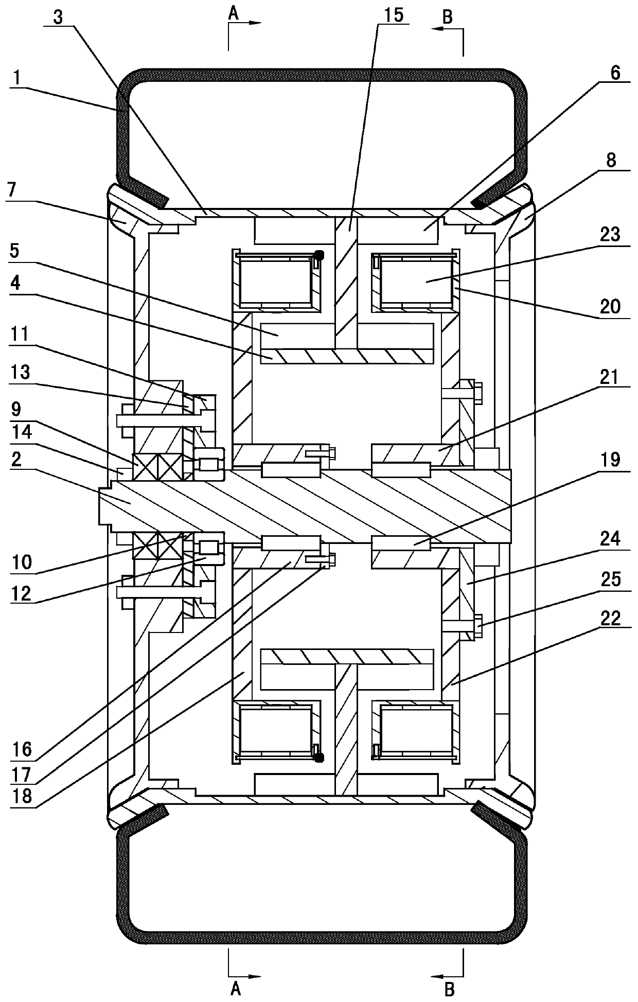
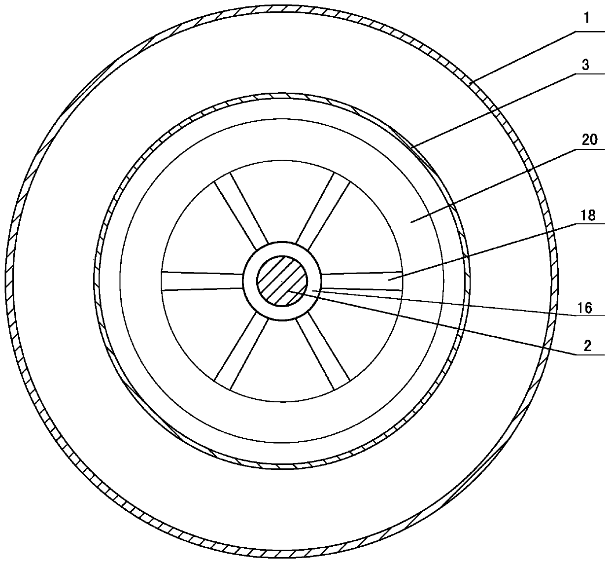
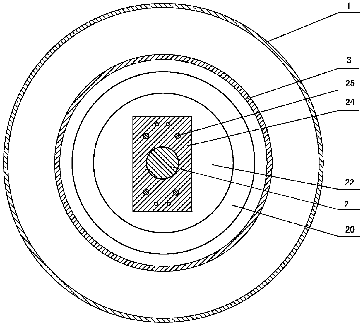
[0021] The technical solutions of the present invention will be further described below in conjunction with the accompanying drawings and embodiments. exist Figure 1-3 In the example shown:

[0022] The rotor assembly includes a cylindrical middle casing 3, a cylindrical base 4, 2 sets of inner ring permanent magnets 5, 2 sets of outer ring permanent magnets 6, and a left casing 7 and a right casing separated on both sides of the middle casing 3. body 8, the middle housing 3 adopts a structure with both sides thick and the middle thin. Among them: the left housing 7 and the right housing 8 are both ring-shaped, set on both ends of the stator shaft 2, the inner end of the left housing 7 is supported on the stator shaft 2 through two angular contact ball bearings 9, the left housing The right side of the body 7 is provided with a first positioning ring 10 and a limit ring 11 in sequence, wherein the inner end of the limit ring 11 is supported on the stator shaft 2 through a c...


PUM


Abstract

The invention provides an in-wheel motor driving wheel which is characterized in that a rotor assembly comprises a cylindrical middle housing, a cylindrical base member, two sets of inner-circle permanent magnets, two sets of outer-circle permanent magnets, and a left housing and a right housing which are arranged at two sides of the middle housing. The outer ends of the left housing and the righthousing are fixedly connected with the middle housing. The middle housing, the left housing and the right housing form a hub-shaped motor housing. A tire is mounted on the outer wall of the middle housing. The two sets of outer-circle permanent magnets and the two sets of inner-circle permanent magnets are correspondingly fixed on the side wall, which faces the base member, of the middle housing,and are arranged at two sides of a supporting member. A left stator assembly comprises a first base, a base spacing ring and a spoke-shaped connector. A right stator assembly comprises a second baseand an annular connecting disc. The outer ends of the connector and the connecting disc are provided with annular stator troughs which are concentric with a stator shaft. The two stator troughs are next to each other and are arranged at two sides of the supporting member. Furthermore the two stator troughs are arranged between the inner-circle permanent magnets and the outer-circle permanent magnets. The numbers of stator windings which are arranged in the two stator troughs are same, and furthermore the stator windings in the two stator troughs correspond with each other.

Description

technical field [0001] The invention relates to a hub motor drive wheel, which belongs to the field of electric vehicle drive. Background technique [0002] With the increasing number of automobiles in China and the increasingly serious problems of energy security and environmental pollution, new energy vehicles have become one of the main directions of China's automobile technology development. In the past ten years, new energy vehicles have made significant contributions to energy conservation and emission reduction, and with the gradual maturity of key technologies of existing new energy vehicles and the further deterioration of environmental problems, people's requirements for energy conservation of new energy vehicles have also gradually increased. The evolution of state support policies can be seen. For example, in 2009, at the beginning of the new energy vehicle industrialization era, mild hybrid vehicles could receive state subsidies; in 2012, the national policy re...

Claims


Application Information

Patent Timeline
Patent Type & Authority Patents(China)
IPC IPC(8): H02K21/22H02K5/04H02K5/173H02K1/12
Inventor 杨坤李鹏程高松王杰展恩昊卢守义
Owner SHANDONG UNIV OF TECH
Learn More