
Head-mounted plane rotation overturning mirror

A plane rotating and flipping mirror technology, which is applied in comprehensive refractometers, eye exercisers, physical therapy, etc., can solve the problems of unstandardized inspection, visual adjustment sensitivity inspection results or inaccurate training, inspection errors, etc.

Pending Publication Date: 2018-04-24
CHONGQING KANGZHI PHARM
View PDF0 Cites 2 Cited by
  • Summary
  • Abstract
  • Description
  • Claims
  • Application Information

AI Technical Summary

Problems solved by technology

[0003] The existing flip mirrors have the following problems: 1. Most of them are hand-held, and the general users are young children. If the time is long, they will be impatient, and the effect of inspection or training will be reduced.
2. In addition, the subject does not see the visual mark through the lens during the hand-held flipping process, which will also cause the distance between the eye and the lens and the distance between the visual mark and the eye. Delay, these factors may cause technical inspection errors
3. At present, there are also some foldable flip mirrors on the market, which use a flip mirror with a positive mirror and a negative mirror superimposed, but this kind of flip mirror that relies on the overlapping of the two mirrors has an impact on the visual quality
4. When switching between positive adjustment and negative adjustment, it all depends on human judgment. For younger users, the inaccuracy of this judgment is relatively large, and the results of visual adjustment sensitivity inspection or training are not accurate.

Method used


Image

  • Head-mounted plane rotation overturning mirror
  • Head-mounted plane rotation overturning mirror
  • Head-mounted plane rotation overturning mirror

Examples


Embodiment Construction

[0027] In order to better illustrate the present invention, the present invention will be described in detail below in conjunction with the accompanying drawings and specific embodiments.

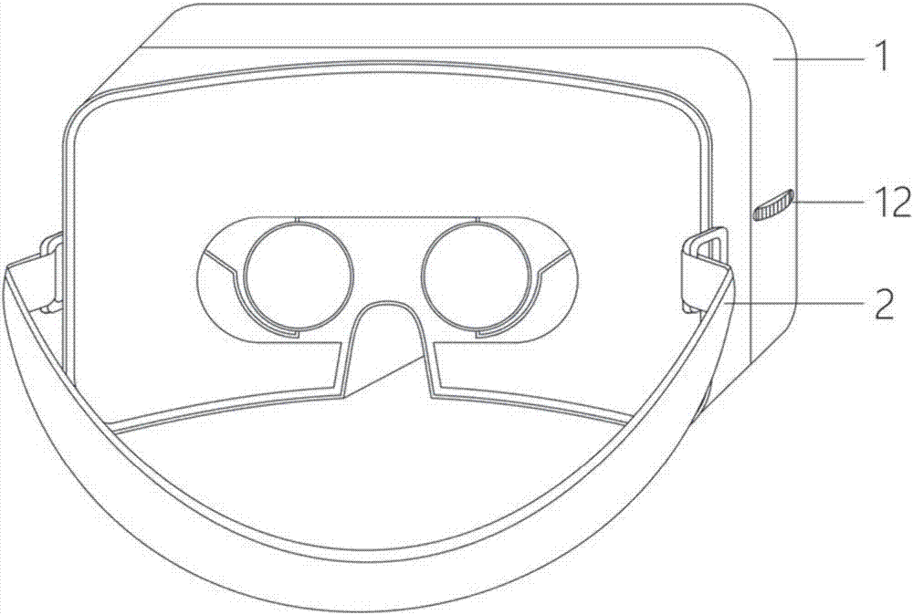
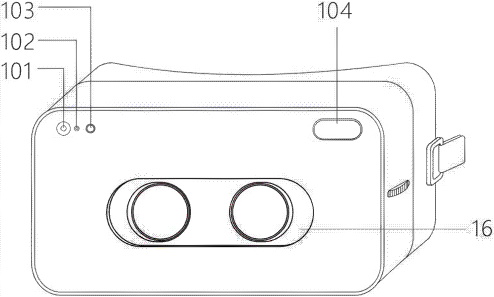
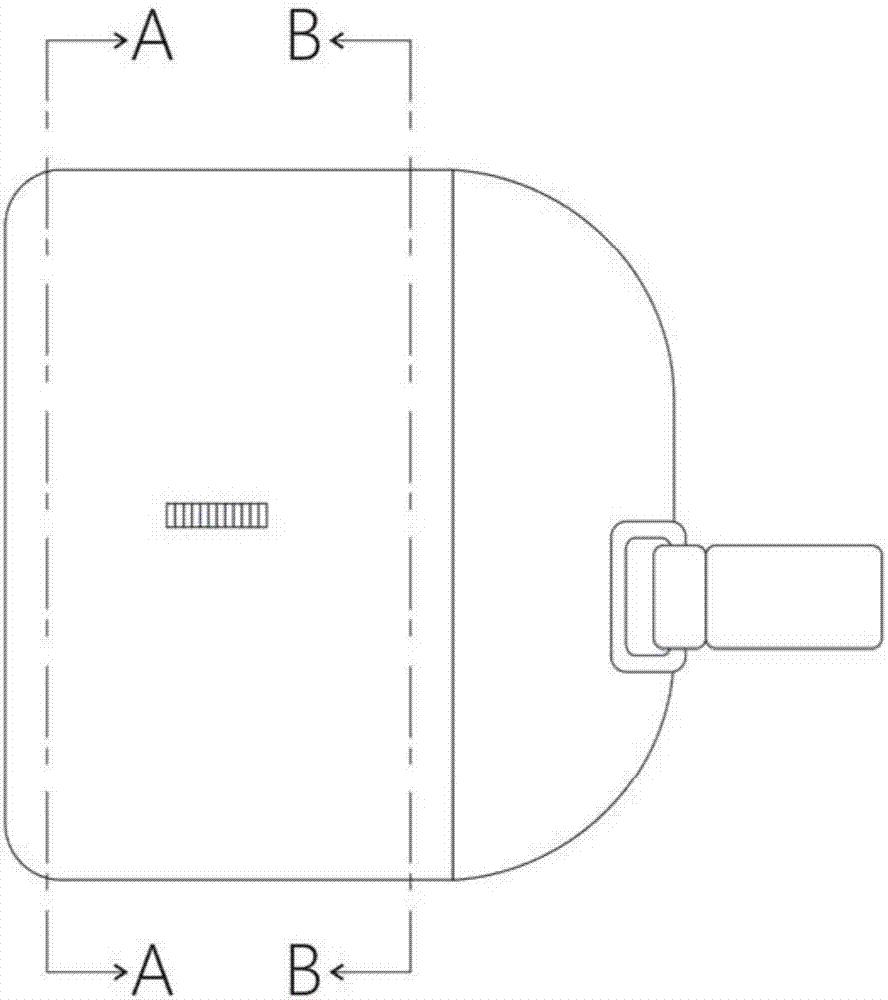
[0028] figure 1 It is the front view of the head-mounted plane rotating flip mirror of the present invention; figure 2 It is the back view of the head-mounted plane rotating flip mirror of the present invention; image 3 It is a side view of the head-mounted plane rotating flip mirror of the present invention; as Figure 1-Figure 3 As shown, the head-mounted flat rotating flip mirror of the present invention includes a shell 1, a headband unit 2 and a PLC control system, the headband unit is arranged on the rear side of the shell, the PLC control system is arranged in the inner cavity of the shell, and the PLC The control system includes a power supply 18, a PLC controller 17, a power switch 101, a mode switch 102, an indicator light 103 and a display screen 104; the left and right sides...


PUM


Abstract

The invention relates to a head-mounted plane rotation overturning mirror. The mirror comprises a shell, a head hoop unit and a PLC control system, the head hoop unit is arranged at the back side of the shell, and the PLC control system is arranged in an inner cavity of the shell; mirror brackets are symmetrically arranged at the left and right sides of the inner cavity of the shell, a rotation mechanism and a mobile mechanism are correspondingly arranged on the mirror brackets one to one, the PLC control system controls the rotation mechanism to drive the mirror brackets, and the rotation mechanism controls the mirror brackets to conduct rotation motion; each mirror bracket is provided with two lenses, the mobile mechanism controls the mirror brackets to horizontally move front and back,a perspective opening which can run through the lenses on the mirror brackets for eye training runs through the shell, and the rotation motion is circular motion that the two lenses are alternativelyrotated to the perspective opening. According to the head-mounted plane rotation overturning mirror, the aim of single-mirror detection and training is achieved, the distance between the center of a correction lens and the top point of the cornea can be finely adjusted, the two eyes are more balanced, and sensitivity adjustment training is conducted by more finely adjusting amplitude variation.

Description

technical field [0001] The invention relates to an instrument for visual adjustment sensitivity inspection and training, in particular to a head-mounted plane rotating flip mirror. Background technique [0002] With the increase in the frequency of use of video terminals, more and more myopia. During the critical period of development, many adolescents and children experience eye fatigue and abnormal adjustment function due to the long time of using their eyes at close range, which leads to myopia. In medicine, the adjustment function of the eye is mainly evaluated from two aspects: the adjustment range and the adjustment sensitivity, and the inspection of the adjustment sensitivity will use a flip mirror. The existing flip mirror is composed of four lenses connected in series by a central axis. One side of the central axis is two positive mirrors, and the other side is two negative mirrors. When in use, the rotation of the central axis drives the positive and negative lens...

Claims


Application Information

Patent Timeline
IPC IPC(8): A61H5/00A61B3/028
CPCA61B3/028A61H5/00A61H2205/024A61H2201/165
Inventor 陈小荣汪春露王文文
Owner CHONGQING KANGZHI PHARM
Learn More