
Valve spring base cold heading forming equipment

A technology for valve springs and forming equipment, which is applied to metal processing equipment, valve devices, manufacturing tools, etc. It can solve problems such as low production efficiency, complex overall structure of equipment, and inability to synchronize cold heading stations to achieve production efficiency. The effect of lifting and the overall structure is simple

Pending Publication Date: 2018-04-24
博峰汽配科技有限公司
View PDF13 Cites 5 Cited by
  • Summary
  • Abstract
  • Description
  • Claims
  • Application Information

AI Technical Summary

Problems solved by technology

At present, there are two main methods of processing and forming the valve spring seat: one is to process the corresponding steps on the formed cylindrical blank by cutting or milling, and then punch holes. This processing method not only has low production efficiency, but also The waste of steel raw materials is serious; the other is to form by cold heading, that is, after cutting the steel into a small section, and then pass through multiple cold forging stations for cold heading, but because each existing cold heading station is in the Work under the respective power sources, so not only the overall structure of the equipment is complicated, but also multiple cold heading stations cannot be operated synchronously, resulting in low production efficiency

Method used


Image

  • Valve spring base cold heading forming equipment
  • Valve spring base cold heading forming equipment
  • Valve spring base cold heading forming equipment

Examples


Embodiment Construction

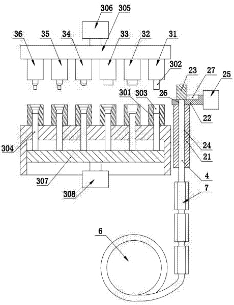
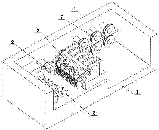
[0017] like Figure 1-5 Shown is a valve spring seat cold heading forming equipment, including an organic base 1, a steel cutting station 2 and a plurality of cold heading stations 3 are arranged side by side on the said machine base 1, each cold heading A mold core 301 and an extrusion ejector pin 302 are all arranged on the station 3, and each mold core 301 is all provided with a concave cavity 303 that is compatible with the corresponding extrusion ejector pin 302, and each cavity 303 also has a A cavity ejector pin 304 for ejecting the formed blank is provided, and a plurality of extrusion ejector pins 302 on a plurality of cold heading stations 3 are all fixed on a die 305, and the die 305 It is connected with an extrusion power source 306 that drives it to move linearly, and a plurality of cavity ejector pins 304 are fixed on a push die 307, and the push die 307 is connected with a push power source 308 that drives it to move linearly. The extruding power source 306 and...


PUM


Abstract

The invention discloses valve spring base cold heading forming equipment. The valve spring base cold heading forming equipment comprises a machine base. A steel cropping station and a plurality of cold heading stations are arranged on the machine base side by side. Each cold heading station is provided with a die core and an extrusion ejector rod. Each die core is provided with a cavity matched with the corresponding extrusion ejector rod. Each cavity is internally further provided with a cavity ejector rod for jacking and conveying a formed blank out. A blank transmitting device is further arranged among the multiple cold heading stations. The blank transmitting device comprises an installing base, the part, corresponding to the position between every two adjacent cold heading stations, of the installing base is provided with a clamping and conveying head, and the installing base is connected to the machine base through a swing arm. By adoption of the above structure, the valve springbase cold heading forming equipment simpler in structure and higher in production efficiency is provided.

Description

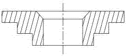
technical field [0001] The invention relates to a processing equipment for forming a valve spring seat by cold heading. Background technique [0002] The valve spring seat is an important part of the engine valve train, and its structure is as follows: figure 1 Shown is cylindrical and has two steps with a central through hole. At present, there are two main methods of processing and forming the valve spring seat: one is to process the corresponding steps on the formed cylindrical blank by cutting or milling, and then punch holes. This processing method not only has low production efficiency, but also The waste of steel raw materials is serious; the other is to form by cold heading, that is, after cutting the steel into a small section, and then pass through multiple cold forging stations for cold heading, but because each existing cold heading station is in the Work under their respective power sources, so not only the overall structure of the equipment is complicated, bu...

Claims


Application Information

Patent Timeline
Patent Type & Authority Applications(China)
IPC IPC(8): B21J1/00B21J5/02B21J13/10B21K1/24B21K27/02B21K27/06
CPCB21J1/00B21J5/008B21J5/025B21J13/10B21K1/24B21K27/02B21K27/06
Inventor 叶多
Owner 博峰汽配科技有限公司
Learn More