
An inverted V-shaped tail connecting structure that is easy to disassemble

A connecting structure and empennage technology, which is applied in transportation and packaging, aircraft stability, fuselage, etc., can solve the problems of difficult disassembly and assembly of the connecting structure, low aerodynamic efficiency, and inability to adjust the installation angle.

Active Publication Date: 2020-10-30
BEIHANG UNIV
View PDF7 Cites 0 Cited by
  • Summary
  • Abstract
  • Description
  • Claims
  • Application Information

AI Technical Summary

Problems solved by technology

[0003] In order to solve the shortcomings of the conventional inverted V-shaped tail connection form, such as low aerodynamic efficiency, difficult disassembly of the connection structure, and inability to adjust the installation angle, the present invention proposes an inverted V-shaped tail connection structure that is easy to disassemble and adjust.

Method used


Image

  • An inverted V-shaped tail connecting structure that is easy to disassemble
  • An inverted V-shaped tail connecting structure that is easy to disassemble
  • An inverted V-shaped tail connecting structure that is easy to disassemble

Examples


Embodiment Construction

[0023] Below in conjunction with accompanying drawing, the present invention is described in further detail.

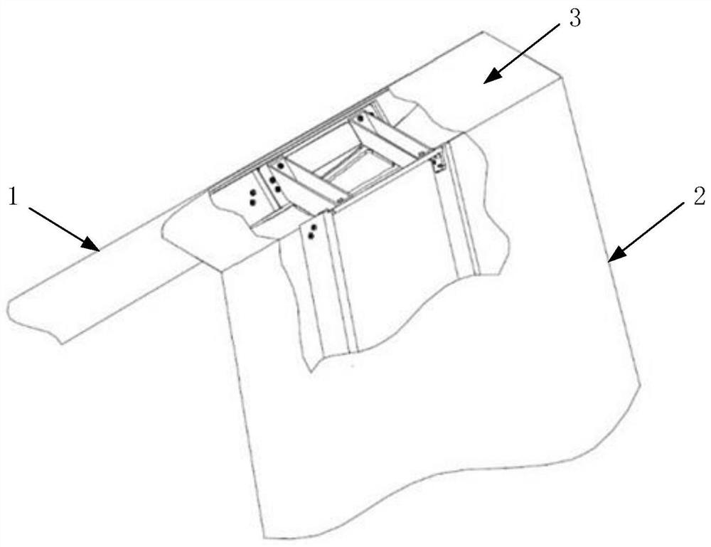
[0024] A kind of inverted V-shaped tail connecting structure that is convenient to disassemble of the present invention comprises left side V tail 1, right side V tail 2 and horizontal connecting wing section 3, as figure 1 shown.

[0025] The bottoms of the left V tail 1 and the right V tail 2 are respectively fixed to the tail of the fuselage, and the tops are connected by the horizontal connecting wing section 2; and there is a smooth transition between the outer skin of the horizontal connecting wing section 3; thereby increasing The width of the flow field at the top of the V-tail is increased, thereby reducing the mutual interference between the empennages and improving the aerodynamic efficiency of the empennages. However, the left V-tail of the conventional inverted V-tail is directly connected to the top of the right V-tail, forming a triangular area. The fl...


PUM


Abstract

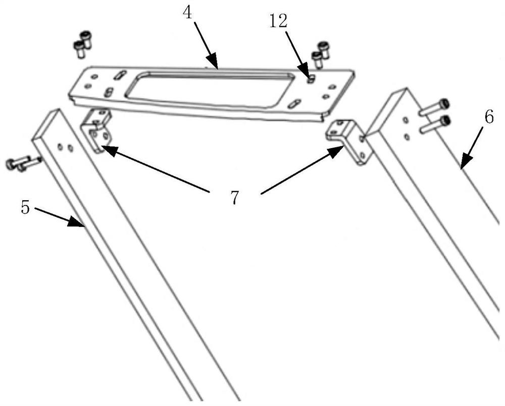
The invention discloses an inverted-V-shaped empennage connecting structure convenient to dismount and mount. The tops of a left V-shaped empennage and a right V-shaped empennage are connected througha horizontal connecting wing section, and an assembling separating plane is perpendicular to a V-shaped empennage mounting angle adjusting shaft; the ends of the V-shaped empennages are provided witha reinforcing rib which is connected with a V-shaped empennage front beam web plate and a V-shaped empennage rear beam web plate through cornual plates, and the reinforcing rib are flanged to increase the connecting area of the reinforcing rib and a skin; a main force bearing part of the horizontal connecting wing section is a front connecting box and a rear connecting box, the front connecting box and the rear connecting box are connected as a whole through a bottom plate and then connected with the V-shaped empennage reinforcing rib through bolts to form a closed type structure; a connecting wing section skin and an inverted V-shaped empennage skin are smoothly transitional, the upper surface of the horizontal connecting wing section is provided with an opening cover, and dismounting and mounting of the bolts are convenient; and the V-shaped empennage reinforcing rib is provided with a bolt connecting groove, and the V-shaped empennage mounting angle can be changed by adjusting positioning of the bolts. According to the inverted-V-shaped empennage connecting structure convenient to dismount and mount, the requirement of the connection strength of the structure is met, the dismounting and mounting convenience, maintainability and adjusting flexibility of the structure are further taken into account, the aerodynamic efficiency of the inverted-V-shaped empennage is improved, and the inverted-V-shaped empennage connecting structure convenient to dismount and mount is very suitable for detachable multi-task light and small type inverted V-shaped layout unmanned aerial vehicles capable of being dismounted and mounted.

Description

technical field [0001] The invention relates to the structure design of a light and small unmanned aerial vehicle, in particular to an inverted V-shaped tail connection structure that is convenient for disassembly and adjustment, and belongs to the technical field of aviation aircraft and mechanical design. Background technique [0002] The inverted V-shaped tail layout is a common aircraft tail layout form. Compared with the normal tail, the inverted V-shaped tail has the advantages of small aerodynamic resistance, good stealth performance, and light structure weight. It is mainly used for twin fuselages or double tails. layout of the aircraft. Structurally, the inverted V tail connects the tails of the two fuselages, greatly increasing the overall structural strength between the fuselages. The connection structure between the inverted V-shaped tail fins is a key force-transmitting component. It not only needs to meet the connection strength requirements of the overall str...

Claims


Application Information

Patent Timeline
Patent Type & Authority Patents(China)
IPC IPC(8): B64C1/26B64C5/00
CPCB64C1/26B64C5/00
Inventor 马东立郭阳胡浩德杨穆清李陟
Owner BEIHANG UNIV
Learn More