Flange type torque sensor

A torque sensor and flange-type technology, which is applied in the field of flange-type torque sensors, can solve the problems of increasing zero drift and affecting detection results, etc., and achieve good lateral protection ability, avoid resonance, and small space effects

Pending Publication Date: 2018-04-24
BEIJING SHITONG KECHUANG TECH
View PDF1 Cites 10 Cited by
  • Summary
  • Abstract
  • Description
  • Claims
  • Application Information

AI Technical Summary

Problems solved by technology

[0004] At present, the Chinese patent with the publication number CN104792445A discloses a wireless linkage torque sensor. The torque sensor includes: a main part, which is the main part of the torque sensor; the left flange is connected to the left torsion plate through eight bolts, and the left There are four countersunk threaded through holes on the small end of the flange, which are used to connect and fix the tested part; the right flange is connected to the right torsion plate through eight bolts, and there are four countersunk holes on the small end of the right flange. The threaded through hole is used to connect and fix the tested part; the strain gauge is pasted in the middle of the elastic body. The strain gauge is a component that senses the torque signal and can convert the mechanical strain of the elastic body into a change in resistance. Due to the left flange and the right Both flanges can be connected to the tested part, one of the flanges is used as the tested part, and the other flange needs to be installed with a driving part, such as a motor, to drive the entire flange to rotate. The flange torque sensor needs It is installed between the motor and the tested part through the flange, and when the flange is installed, one end of the left and right flanges is connected to the tested part and the other end is connected to the driving part. The angle error after the left and right flanges are fixed will make the flange shaft in the There is a small deformation before the force is applied, and the elastic body installed in the shaft hole and the strain gauge attached to the elastic body will also be slightly deformed under the influence of it, forming a static stress that counteracts the deformation. Before the test, this stress will make the test starting position of the strain gauge higher than the zero point, that is, increase its zero point drift and affect the test result

Method used


Image

  • Flange type torque sensor
  • Flange type torque sensor
  • Flange type torque sensor

Examples


Embodiment 1

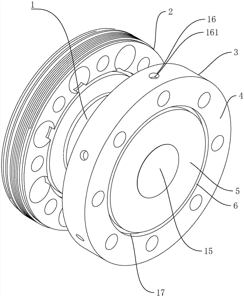
[0038] Embodiment 1: a kind of flange type torque sensor, such as figure 1 As shown, it includes the flange shaft 1, the left flange 2 and the right flange 3 arranged at both ends of the flange shaft 1, the left flange 2 is connected to the power input end, the power input end can be a motor, and the right flange Disk 3 is connected to the load detection end, which can be a rotating shaft that extends into the reactor to contact the liquid. Because the load detection end is in contact with the liquid, the consistency of the liquid loads the rotating shaft, and finally generates torque at the position of the flange shaft 1. , and calculate the consistency by detecting the torque value correspondingly.

[0039] Such as figure 2 As shown, the left and right flanges have an outer ring 4 connected to the power input end or a load detection end, and an inner ring 5 connected to the flange shaft 1. The outer ring 4 and the inner ring 5 are integrally arranged. There is a shaft hol...

Embodiment 2

[0048] Embodiment 2: a flange type torque sensor, the difference from Embodiment 1 is that, as Figure 7 As shown, the stress isolation grooves 6 on the end faces of the left flange 2 and / or the right flange 3 are distributed to the two axial end faces of the left flange 2 and / or the right flange 3, and the left method The diameter of the stress isolation groove 6 on the outer end surface of the flange plate 2 and / or the right flange plate 3 is larger or smaller than the stress isolation groove 6 on the inner end surface.

[0049] The rotation of the motor acts on the outer ring 4 of the left flange 2 to transmit the stress generated during the rotation. According to the stress isolation groove 6 with different diameters on the inner ring 5 and the outer ring 4, the stress generated when the motor rotates Two times of transitional dispersion at the positions of the two stress isolation grooves 6 along the meridian direction, only a small amount of stress is transmitted to the ...

Embodiment 3

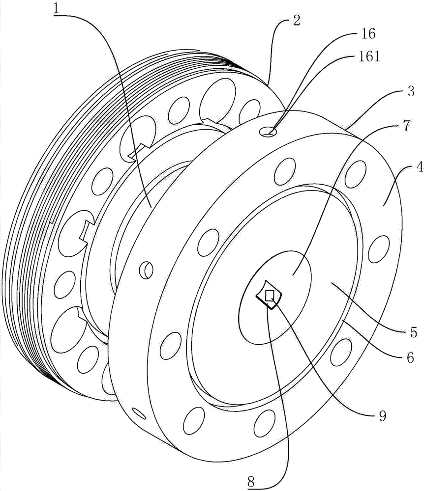
[0050] Embodiment 3: a flange type torque sensor, the difference from Embodiment 1 is that reference Figure 8 , a flange type torque sensor, including a flange shaft 1, left and right flanges 3 arranged at both ends of the flange shaft 1, the left flange 2 is connected to the power input end, and the right flange 3 is connected to the load detection end , the left and right flanges 3 have an outer ring 4 connected to the power input end or a load detection end, and an inner ring 5 connected to the flange shaft 1, the flange shaft 1 is provided with a shaft hole 7, and the inner wall of the shaft hole 7 is provided with There are elastic bodies 8 and strain gauges 9, the outer ring 5 and the inner ring 4 are integrally arranged, and the end faces of the left flange 2 and / or right flange 3 are provided to axially isolate the outer ring 5 from the inner ring 4 The groove 17, the groove 17 is formed by the inner ring 4 being concave, and the inner ring 4 and the outer ring 5 are ...


PUM


Abstract

The invention discloses a flange type torque sensor, which comprises a flange shaft, left and right flange plates arranged at both ends of the flange shaft, the left flange plate is connected with the power input end, the right flange plate is connected with the load detection end, and the left and right flange plates are connected with the load detection end. The flange has an outer ring connected to the power input end or load detection end, and an inner ring connected to the flange shaft. The flange shaft is provided with a shaft hole, and the inner wall of the shaft hole is provided with an elastic body and a strain gauge. The outer ring It is integrally arranged with the inner ring, and the end surface of the left flange and/or the right flange is provided with an isolation part for isolating the outer ring and the inner ring. In this way, when the left and right flanges are respectively connected between the motor and the load to be detected, after the isolation part is set between the outer ring and the inner ring, the bolt link position on the flange is isolated from the position directly connected to the flange shaft in the middle, Avoid the above-mentioned static stress from being transmitted to the strain gauge, so as to minimize its deformation under the influence of non-detection stress, that is, minimize zero drift.

Description

technical field [0001] The invention relates to the field of measuring devices, in particular to a flange type torque sensor. Background technique [0002] The torque sensor is an instrument for measuring the torque signal of the equipment, which is divided into two categories: dynamic and static. Among them, the dynamic torque sensor can also be called torque sensor, torque speed sensor, non-contact torque sensor, rotary torque sensor, etc. Torque sensors are used to detect the perception of torsional torque on various rotating or non-rotating mechanical parts, and convert the physical changes of torque into precise electrical signals. [0003] In terms of testing principle, torque sensors can be divided into strain type, magnetoelastic type, magnetoelectric type and other types, etc. The torque measurement of strain gauge sensor adopts strain electrical measurement technology. The strain type torque sensor is to paste the resistance strain gauge on the specified position ...

Claims


Application Information

Patent Timeline
Patent Type & Authority Applications(China)
IPC IPC(8): G01L3/10
CPCG01L3/108
Inventor 时大卫童小海
Owner BEIJING SHITONG KECHUANG TECH
Why Eureka
Try Eureka