Reflection lens and ultra-thin backlight module thereof

A reflective lens and backlight module technology, applied in the field of lens and backlight, can solve the problems of reducing overall thickness, temperature rise, light energy loss, etc., to reduce the number of PCB boards, improve brightness uniformity, and improve corner brightness. Effect

Pending Publication Date: 2018-04-24
NINGBO ZHENGTE OPTICAL ELECTRIC APPLIANCE
View PDF5 Cites 3 Cited by
  • Summary
  • Abstract
  • Description
  • Claims
  • Application Information

AI Technical Summary

Problems solved by technology

The light emitted by the LED of the traditional side-type backlight module needs to be scattered by the dots of the light guide plate and refracted by the light guide plate, so that the LED light source entering the side light is converted into a surface light source output from the front, and the multiple scattering of the dots and the light guide plate Refraction causes serious loss of light energy, resulting in low light efficiency of the side-lit backlight module and low brightness of the display screen
[0004] The traditional direct-type backlight module and side-type backlight module deliberately reduce the thickness of the side for the sake of beautiful appearance. Due to the internal structure of the direct-type backlight module and the side-type backlight module, the reduced side thickness is the same as Reducing the overall thickness also means that the space inside the TV is getting smaller and smaller, causing the panels to be squeezed together. This kind of layout compromised for the appearance will lead to poor heat dissipation of the TV, and the temperature will rise, and the TV will also be reduced due to high temperature. Life to failure

Method used


Image

  • Reflection lens and ultra-thin backlight module thereof
  • Reflection lens and ultra-thin backlight module thereof
  • Reflection lens and ultra-thin backlight module thereof

Examples


Embodiment Construction

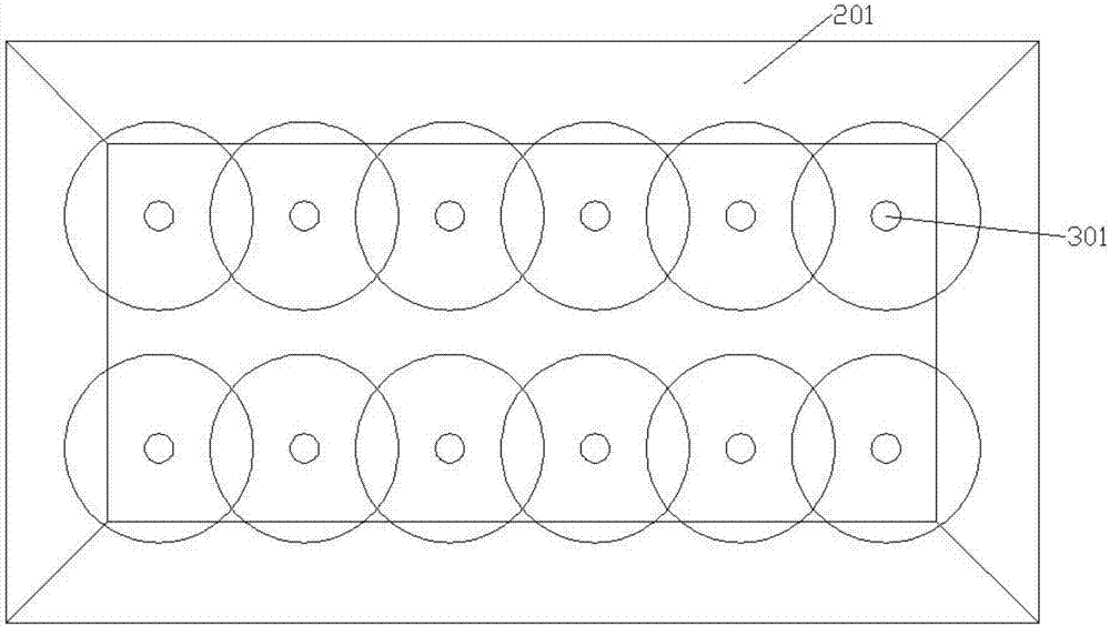
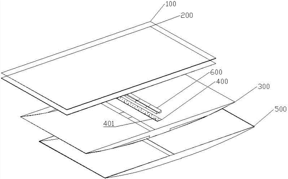
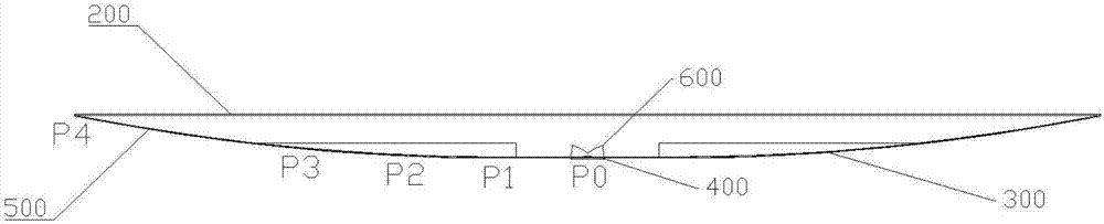
[0040] refer to Figure 2 to Figure 9 , the present invention provides a reflective lens and its ultra-thin backlight module, see Figure 5 , Figure 6 and Figure 7 In this embodiment, the reflective lens 600 is composed of two symmetrical parts, and the overall shape is roughly rectangular; the reflective lens 600 includes an exit surface 601, an incident surface 602, a bottom fog surface 603, a column base 604 and a reflection surface 605, see Figure 7 , the column foot 604 is installed on the bottom matte surface 603, the incident surface 602 is a left-right symmetrical concave shape, the external CSP light source 401 is located at the concave center of the incident surface 602, the bottom matte surface 603 is connected with the incident surface 602; the exit surface 601 are respectively connected to the bottom matte surface 603 and the reflective surface 605; the outgoing surface 601 and the reflective surface 605 are symmetrically arranged on the left and right sides ...


PUM


Abstract

The invention provides a reflection lens and an ultra-thin backlight module thereof. The reflection lens comprises an emergent surface, an incident surface, a bottom fog surface, column feet and a reflection surface. The column feet are arranged on the bottom fog surface. The incident surface is in a left-right symmetrical type inwardly concave shape. An external CSP light source is located at thecenter position of the inwardly concave shape of the incident surface. The bottom fog surface is connected with the incident surface. The emergent surface is connected with the bottom fog surface andthe reflection surface respectively. The emergent surface and the reflection surface are symmetrically arranged on the left side and the right side of the incident surface respectively. The ultra-thin backlight module comprises an optical diaphragm, a diffusion plate, a reflective paper, a lamp strip and a cavity. The reflection lens is good in transmission effect, and the backlight module is uniform in brightness, good in light effect, low in cost and attractive in appearance.

Description

technical field [0001] The invention relates to the technical field of lenses and backlights, in particular to a reflective lens and an ultra-thin backlight module. Background technique [0002] Currently in the field of liquid crystal display, since the liquid crystal molecules themselves do not have the ability to emit light, an external light source is required to obtain the display screen in the existing liquid crystal display. At present, the light source mostly uses LED light-emitting diodes, which are diffused and homogenized by the backlight module. Extend the LED light source to surface light output. At this stage, the backlight modules of display devices can be divided into two types: side-type and direct-type. Compared with side-type backlight modules, direct-type backlight modules do not need to be equipped with light guide plates, so they are cheaper and more popular. Welcomed by the majority of consumers. Compared with direct-lit backlight modules, side-lit b...

Claims


Application Information

Patent Timeline
IPC IPC(8): G02B3/00G02B5/08G02F1/13357
CPCG02F1/133605G02F1/133606G02F1/133611G02B3/00G02B5/0808G02F1/133607
Inventor 章奇
Owner NINGBO ZHENGTE OPTICAL ELECTRIC APPLIANCE
Why Eureka
Try Eureka