A heat-shrinkable tube delivery mechanism

A technology of conveying mechanism and heat-shrinkable tube, which is applied in the assembly/disassembly of contact parts, connection insulation, etc., which can solve the problems of difficult to ensure the tube body, avoid artificial damage to heat-shrinkable tubes, improve the efficiency of packaging and the quality of packaging, The effect of improving the conveying efficiency

Active Publication Date: 2019-07-26
涟水满贯科技有限公司
View PDF5 Cites 0 Cited by
  • Summary
  • Abstract
  • Description
  • Claims
  • Application Information

AI Technical Summary

Problems solved by technology

Among them, on the delivery module of the heat-shrinkable tube, there is no device for automatically delivering the heat-shrinkable tube in the prior art. At the same time, due to the flexibility of the heat-shrinkable tube, it is difficult to ensure that the tube body remains open during the delivery process.

Method used


Image

  • A heat-shrinkable tube delivery mechanism
  • A heat-shrinkable tube delivery mechanism
  • A heat-shrinkable tube delivery mechanism

Examples


Embodiment 1

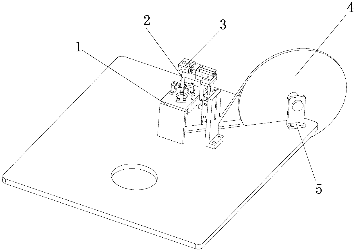
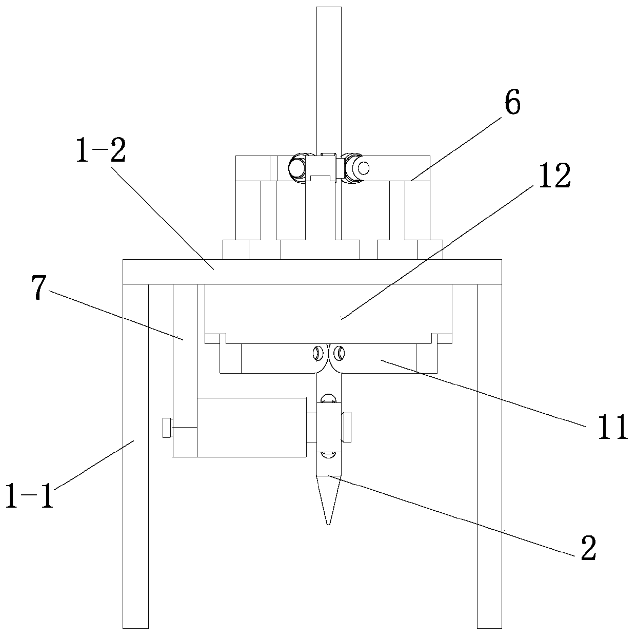
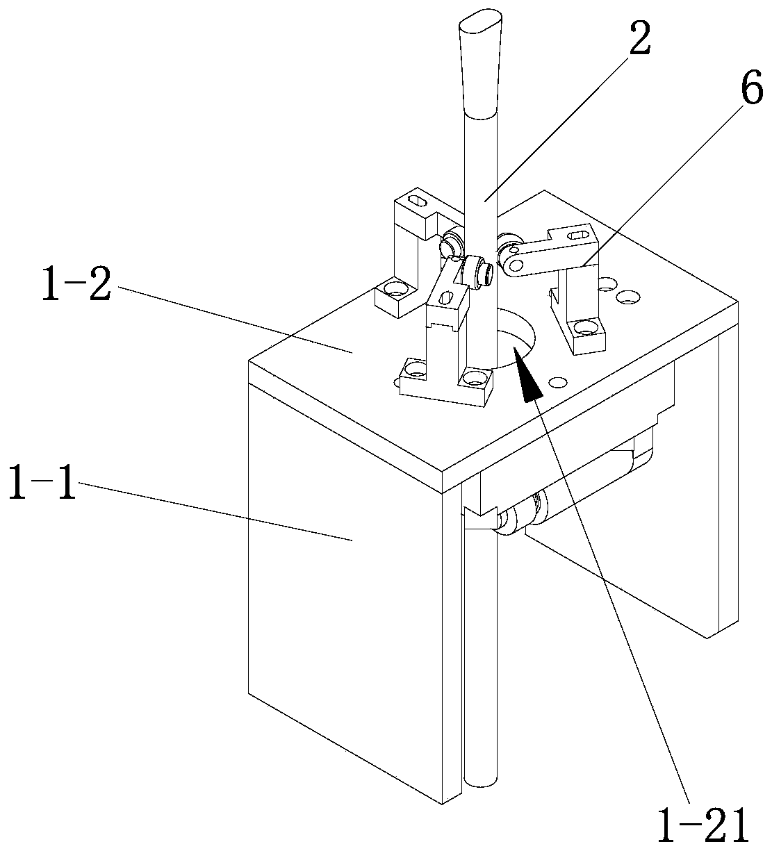
[0044] see Figure 1-Figure 14 , a heat-shrinkable tube delivery mechanism in this embodiment includes a delivery bracket 1, a delivery guide rod 2, a delivery wheel set, and a clamping and pulling mechanism 3 arranged above the delivery guide bar 2; the delivery wheel set includes an inner positioning wheel set And be arranged on the outer locating wheel set on the conveying support 1; Described inner locating wheel set comprises the upper locating wheel 10 and the lower locating wheel 9 that are vertically arranged in the conveying guide bar 2; Described outer locating wheel set includes two Be respectively arranged on the two sides in the middle of the upper positioning wheel 10 and the lower positioning wheel 9 and clamp the upper positioning wheel 10 and the lower positioning wheel 9; the two outer positioning wheels 8 and the upper positioning wheel 10 and The axes of the lower positioning wheels 9 are parallel; the heat-shrinkable tube is sleeved on the conveying guide ...

Embodiment 2

[0060] The difference between this embodiment and embodiment 1 is:

[0061] see Figure 15 , there are two sets of the inner positioning wheel set and the outer positioning wheel set, and the two sets of inner positioning wheel sets are vertically arranged in the conveying guide rod 2 . Two groups of outer locating wheel sets are respectively arranged on both sides in the middle of the upper locating wheel 10 and the middle locating wheel of each group of inner locating wheel sets, and are all compressed towards the middle.

[0062] By arranging two sets of inner positioning wheels and outer positioning wheels, the fixing of the conveying guide rod 2 is more firm, ensuring that the conveying guide rod 2 will not move upwards, thereby further fixing the position of the conveying guide rod 2 .

Embodiment 3

[0064] The difference between this embodiment and embodiment 1 is:

[0065] see Figure 16, In the roller mounting groove 2-2 of the conveying guide bar 2, two sets of inner positioning wheels arranged side by side are arranged, and the inner positioning wheels of the two sets of inner positioning wheels do not interfere with each other. The set of outer locating wheels includes two sets of outer locating wheels 8, wherein the two sets of outer locating wheels 8 are respectively arranged on the outer sides of the two sets of inner locating wheels, and are pressed against the corresponding set of two inner locating wheels. in the middle.

[0066] Since the inner positioning rollers of the two sets of inner positioning wheels do not interfere with each other, when the heat-shrinkable tube is conveyed upwards, the outer positioning wheels 8 can be driven to rotate, and the inner positioning wheels will also rotate, which can significantly reduce heat shrinkage. The friction bet...


PUM


Abstract

The invention discloses a heat-shrinking pipe conveying mechanism. The mechanism comprises a conveying bracket, a conveying guide bar, conveying wheel sets and a clamping and pulling mechanism which is arranged above the conveying guide bar; the conveying wheel sets comprise an inner positioning wheel set and an outer positioning wheel set which is arranged on the conveying bracket; the inner positioning wheel set includes an upper positioning wheel and a lower positioning wheel which are arranged vertically in the conveying guide bar; the outer positioning wheel set includes outer positioningwheels which are arranged at two sides of a space between the upper positioning wheel and the lower positioning wheel and clamp the upper positioning wheel and the lower positioning wheel; the outerpositioning wheel group is parallel to the axes of the upper positioning wheel and the lower positioning wheel; and a heat shrinkable pipe sleeves the conveying guide bar and is clamped between the inner positioning wheel set and an outer roller set. The mechanism of the present invention can automatically convey the heat shrinkable pipe to a sleeving station with the heat shrinkable pipe kept open, and avoid the bending or deviation of the heat shrinkable pipe during a conveying process, thereby improving conveying efficiency, and benefitting the sleeving processing of conductive insert wires.

Description

technical field [0001] The invention relates to a conductive plug-in wire packaging device, in particular to a heat-shrinkable tube conveying mechanism. Background technique [0002] The conductive plug-in wire is a common power cord suitable for charging various electrical appliances, such as the power cord of electric kettles and rice cookers; one end of the conductive plug-in wire is usually composed of two plug-in plugs arranged side by side (or three triangular The other end is connected to the power plug; in the process of use, the plug of the wire plug is matched with the charging place of the electrical appliance, and then the power plug is inserted into the socket, so as to realize the charging of the electrical appliance. [0003] In the production process of the conductive plug-in wire, the plug-in heads of two independent conductive plug-in wires are welded together by relevant processing equipment to form a tail plug, and then the tail plugs of the conductive pl...

Claims


Application Information

Patent Timeline
Patent Type & Authority Patents(China)
IPC IPC(8): H01R43/20H01R4/72
CPCH01R4/72H01R43/20
Inventor 王瑞长冼柏恩
Owner 涟水满贯科技有限公司
Why Eureka
Try Eureka