A Generator Base with Protective Function
A protection function and generator technology, applied in the direction of electromechanical devices, electrical components, electric components, etc., can solve problems such as maintaining the stability of the generator, and achieve the effects of protection safety, simple structure, and complex structure
Active Publication Date: 2019-10-01
江西省一互电气有限公司
View PDF8 Cites 0 Cited by
- Summary
- Abstract
- Description
- Claims
- Application Information
AI Technical Summary
Problems solved by technology
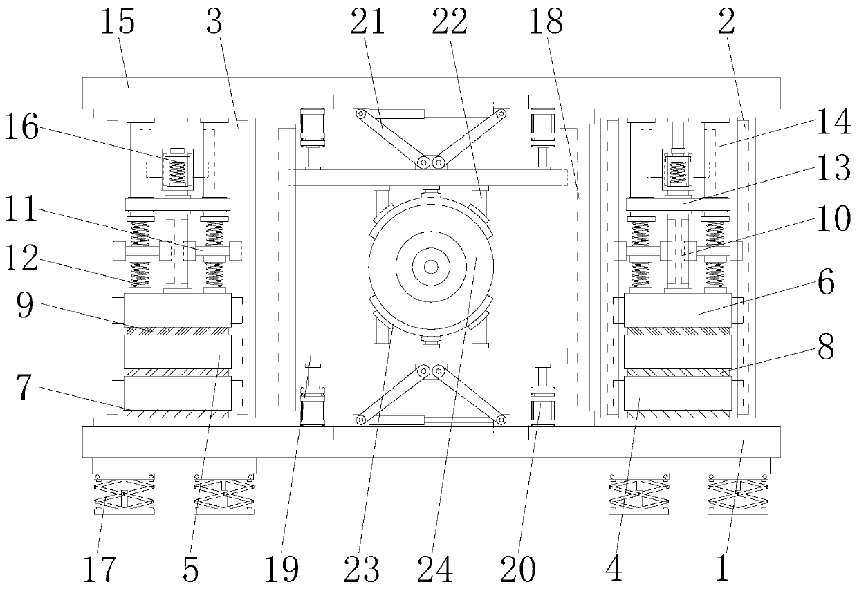
Aiming at the deficiencies of the prior art, the present invention provides a generator base with a protective function, which solves the problem that the existing generator base with a protective function cannot keep the generator stable when the generator falls to the ground, and ensures that the generator problem that won't pop up
Method used
View moreImage
Smart ImageViewing Examples
Examples
Embodiment Construction
Login to View More PUM
 Abstract
The invention discloses a power generator base with a protection function. The power generator base comprises a bottom plate. Two sides of the top of the bottom plate are fixedly connected to first support rods. One side of each of the first support rods is fixedly connected to a second support rod at the top of the bottom plate. The bottoms of second damper blocks are fixedly connected to secondary buffer boards. The invention relates to the technical field of a power generator protection base. According to the power generator base with a protection function, two sides of the top of the bottom plate are fixedly connected to the first support rods, a condition that a power generator does not pop up when the power generator falls to the ground is ensured, the protection of the power generator is stronger, thus the power generator is not damaged after falling to the ground, the damage in falling is reduced, the safety of the power generator is greatly protected, thus the service life ofthe power generator is longer, and the problem that an existing power generator base with a protection function can not maintain the stability of the power generator when the power generator falls tothe ground and can not prevent the popup of the power generator is solved.
Description
technical field The invention relates to the technical field of a generator protection base, in particular to a generator base with a protection function. Background technique A generator is a mechanical device that converts other forms of energy into electrical energy. It is driven by a water turbine, steam turbine, diesel engine or other power machinery, and converts the energy generated by water flow, air flow, fuel combustion or nuclear fission into mechanical energy and transmits it to the generator. The generator is converted into electric energy. The generator has a wide range of uses in industrial and agricultural production, national defense, science and technology and daily life. Whether it is a diesel generator or a gasoline generator, each cylinder performs work in a certain order and acts on the piston. The thrust on the engine turns into the power to drive the crankshaft through the connecting rod, thereby driving the crankshaft to rotate. If the brushless sync...
Claims
Login to View More Application Information
Patent Timeline
 Patent Type & Authority Patents(China)
IPC IPC(8): H02K5/24
Inventor 刘新林
Owner 江西省一互电气有限公司
Features
- R&D
- Intellectual Property
- Life Sciences
- Materials
- Tech Scout
- Unparalleled Data Quality
- Higher Quality Content
- 60% Fewer Hallucinations
Learn More Browse by: Latest US Patents, China's latest patents, Technical Efficacy Thesaurus, Application Domain, Technology Topic, Popular Technical Reports.
© 2025 PatSnap. All rights reserved.Legal|Privacy policy|Modern Slavery Act Transparency Statement|Sitemap|About US| Contact US: help@patsnap.com


