
Tube type heat exchanger

A tube-and-tube heat exchanger and heat exchanger technology, applied in the direction of heat exchanger type, heat exchanger shell, indirect heat exchanger, etc., can solve the problem of temperature difference stress, easily damaged heat exchanger, short service life, etc. problems, to achieve the effect of prolonging the service life and eliminating water leakage

Inactive Publication Date: 2018-04-27
HUAIAN SHENGYU ELECTRONICS
View PDF0 Cites 6 Cited by
  • Summary
  • Abstract
  • Description
  • Claims
  • Application Information

AI Technical Summary

Problems solved by technology

[0003] However, there are still many deficiencies in the current shell and tube heat exchangers.
For example, it is easy to form scale blockage, inconvenient cleaning, serious leakage, temperature difference stress, easy damage to heat exchanger, and short service life

Method used


Image

  • Tube type heat exchanger

Examples


Embodiment Construction

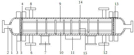
[0012] The present invention will be specifically described below in conjunction with the accompanying drawings and specific embodiments.

[0013] Such as figure 1 As shown, the present invention is a tube-and-tube heat exchanger, which mainly consists of a cylinder body 1, a tube box 2, a nut 3, a tube plate 4, a gasket 5, a drain port 6, a support 7, an exhaust port 8, The heat exchanger 9, the pipe 10, the cleaning port 11, the shell side connecting pipe 12, the equipment flange 13, the heat insulation layer 14, and the baffle plate 15 are composed. The front end of the cylinder 1 is fixedly connected with the tube box 2, and the Two tube sheets 4 are arranged inside the front end and the rear end of the cylinder body 1. The tube sheets 4 are screwed to the cylinder body 1 through nuts 3. The tube sheets 4 are fixedly connected to both ends of the heat exchanger 9. The lower end of the heat exchanger 9 is provided with a tube 10, the middle of the heat exchanger 9 is provi...


PUM


Abstract

The invention discloses a tube type heat exchanger. The tube type heat exchanger is mainly composed of a barrel, a tube header, nuts, tube plates, a spacer, a liquid discharging outlet, a support, anair vent, a heat exchanger body, a tube, a cleaning opening, a shell pass connection pipe, an equipment flange, a heat insulating layer and a baffle plate, wherein the front end of the barrel is fixedly connected with the tube header; the two tube plates are arranged inside the front end and the rear end of the cylinder separately, and the tube plates are in threaded connection with the cylinder through the nuts and are fixedly connected with the two ends of the heat exchanger body; the tube is arranged at the lower end of the heat exchanger body; the baffle plate is arranged in the middle ofthe heat exchanger body; the liquid discharging outlet is formed in the lower portion of the front end of the cylinder; the lower portion of the rear end of the cylinder is fixedly connected with theshell pass connection pipe; the lower end of the cylinder is fixedly connected with the support; the cleaning opening is formed in the middle of the support and is in threaded connection with the lower end of the cylinder; the rear end of the cylinder is in threaded connection with the equipment flange; and the inner wall of the cylinder is fixedly connected with the heat insulating layer. The tube type heat exchanger has the technical effects that cleaning is convenient, the service life is prolonged, and no water leakage exists.

Description

technical field [0001] The invention relates to the field of electronic products, in particular to a tube-and-tube heat exchanger. Background technique [0002] The shell and tube heat exchanger is the most widely used heat exchanger in chemical and alcohol production. It is mainly composed of shell, tube sheet, heat exchange tube, head, baffle and so on. During heat exchange, one kind of fluid enters from the connecting pipe of the head, flows in the pipe, and flows out from the outlet pipe at the other end of the head, which is called the tube side; The other pipe on the shell flows out, which is called a shell-side shell-and-tube heat exchanger. If the inlet and outlet temperature of the hot fluid for the purpose of cooling in the heat exchanger has been determined by the process conditions, the outlet temperature of the cooling medium needs to be selected. If you choose a higher outlet temperature, you can choose a small heat exchanger, but the flow rate of the coolin...

Claims


Application Information

Patent Timeline
Patent Type & Authority Applications(China)
IPC IPC(8): F28D7/16F28F9/24F28F9/12F28F9/10
CPCF28D7/16F28F9/10F28F9/12F28F9/24
Inventor 宗启军
Owner HUAIAN SHENGYU ELECTRONICS
Learn More