Dynamic monitoring system and method of insecticidal lamp

A technology of dynamic monitoring and insecticidal lamps, which is applied in signal transmission systems, closed-circuit television systems, devices for catching or killing insects, etc., can solve the problem of poor monitoring of insecticidal conditions, single function of insecticidal lamps, Unfavorable promotion and popularization and other issues, to achieve the effect of favorable promotion and popularization, simple and reasonable structural design, and wide application range

Inactive Publication Date: 2018-05-01
四川瑞进特科技有限公司
View PDF5 Cites 4 Cited by
  • Summary
  • Abstract
  • Description
  • Claims
  • Application Information

AI Technical Summary

Problems solved by technology

However, when the insecticidal lamps in the prior art are used outdoors, they cannot monitor the insecticidal situation very well, and the number of insects killed at night can only be known by going to the scene to observe. It is very inconvenient to judge the number of pests in this area, and the existing insecticidal lamps have relatively single functions. With the development of the Internet, they are increasingly unable to meet people's needs, which is not conducive to extensive promotion and popularization.

Method used


Image

  • Dynamic monitoring system and method of insecticidal lamp
  • Dynamic monitoring system and method of insecticidal lamp
  • Dynamic monitoring system and method of insecticidal lamp

Examples


Embodiment Construction

[0023] The following will clearly and completely describe the technical solutions in the embodiments of the present invention with reference to the accompanying drawings in the embodiments of the present invention. Obviously, the described embodiments are only some, not all, embodiments of the present invention. The specific embodiments described here are only used to explain the present invention, not to limit the present invention. Based on the embodiments of the present invention, all other embodiments obtained by persons of ordinary skill in the art without making creative efforts belong to the protection scope of the present invention.

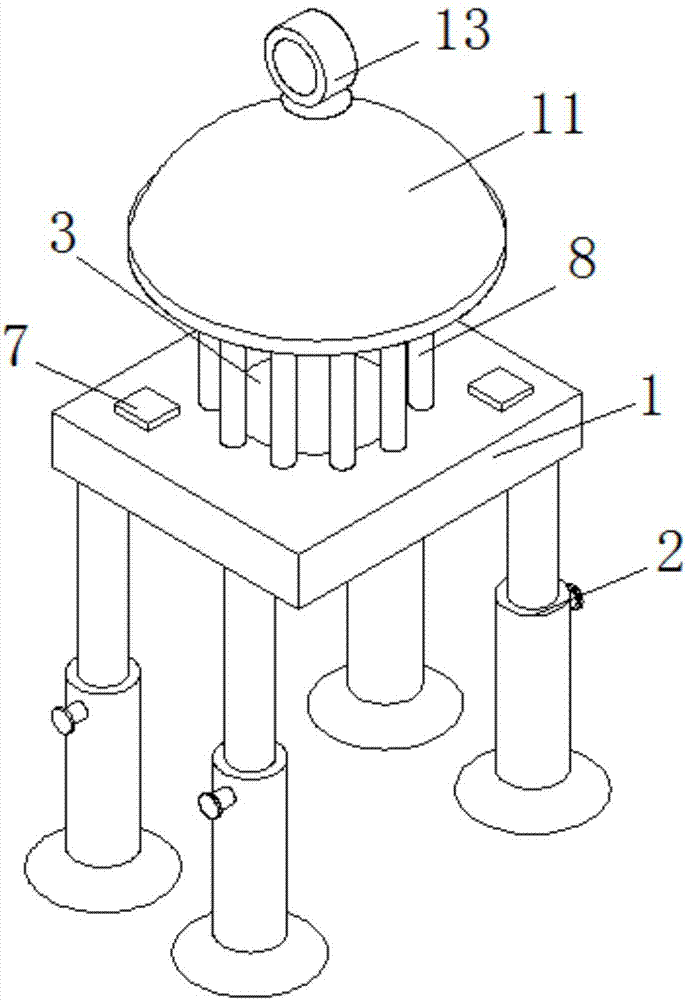
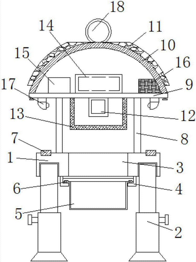
[0024] The present invention provides such as Figure 1-3 The insecticidal lamp dynamic monitoring system shown includes a base 1, four sets of telescopic rods 2 are threadedly connected to the bottom corner of the base 1, and a through hole 3 is provided in the middle of the top of the base 1, and the base 1 The bottom of the bottom of ...


PUM


Abstract

The invention discloses a dynamic monitoring system and method of an insecticidal lamp. The system comprises a base, a through hole is formed in the middle of the top of the base, and an insect collection box is slidingly connected with the bottom of the base; a column is welded to the portion, at the outer side of the through hole, on the top of the base, a top plate is fixedly arranged on the top of the column, and a shell is fixedly arranged on the top of the top plate through a screw thread; an ultraviolet lamp is fixedly arranged in the middle of the bottom of the top plate, a power gridsleeves the portion, at the outer side of the ultraviolet lamp, of the bottom of the top plate, and a DSP controller and a wireless communicator are arranged at the two sides of the top of the top plate respectively; a night vision camera is fixedly arranged on the portion, at the outer side of the column, on the bottom of the top plate, and sensor components are symmetrically embedded in the corners of the two sides of the top of the base. The dynamic monitoring system of the insecticidal lamp is simple and reasonable in structural design and convenient to operate, the use effect of the insecticidal lamp is guaranteed, the working state of the insecticidal lamp is monitored in real time at the same time, and the system is diverse in function, safe, stable, wide in application range and beneficial to popularization and generalization.

Description

technical field [0001] The invention belongs to the technical field of insecticidal lamps, specifically relates to a dynamic monitoring system for insecticidal lamps, and also relates to a monitoring method for the dynamic monitoring system of insecticidal lamps. Background technique [0002] Insecticidal lamp is a special device based on the phototaxis of insects, using insect-sensitive light sources in specific spectral ranges to trap insects and effectively kill insects, reduce the index of diseases and insect pests, and prevent and control insect pests and insect-borne diseases. It is mainly used to kill pests and reduce the use of pesticides. However, when the insecticidal lamps in the prior art are used outdoors, they cannot monitor the insecticidal situation very well, and the number of insects killed at night can only be known by going to the scene to observe. It is very inconvenient to judge the number of pests in this area, and the existing insecticidal lamps have...

Claims


Application Information

Patent Timeline
Patent Type & Authority Applications(China)
IPC IPC(8): A01M1/04A01M1/22H04N7/18G08C17/02G01V8/10
CPCA01M1/04A01M1/223G01V8/10G08C17/02H04N7/18
Inventor 何海洋
Owner 四川瑞进特科技有限公司
Why Eureka
Try Eureka