Lifting chute
A technology of chute and lifting device, applied in the field of lifting chute, can solve the problems of incapable of moving the feeding equipment for feeding, the connection between the feeding port and the discharging port of the feeding equipment, etc., to achieve the effect of accurate feeding
- Summary
- Abstract
- Description
- Claims
- Application Information
AI Technical Summary
Problems solved by technology
Method used
Image

Examples
specific Embodiment approach
[0021] Lifting chute of the present invention, its preferred embodiment is:
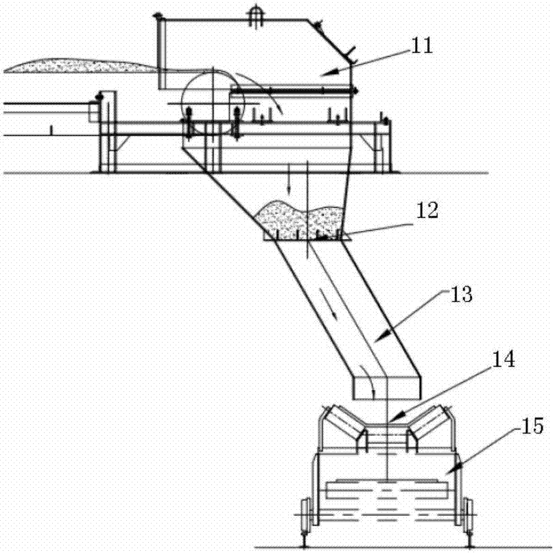
[0022] It includes a discharge belt head, a lifting chute, and a discharge port of the chute. The lifting chute includes two mutually nested telescopic joints, and a lifting device is arranged between the two parts of the telescopic joint.
[0023] The lifting device includes an electro-hydraulic push rod connected between two parts of the telescopic joint.
[0024] The lifting device also includes a spring connected between the two parts of the telescopic joint.
[0025] The lifting chute of the present invention is normally in a raised state. When the feeding equipment moves, the chute will not block the movement of the equipment. When the mobile equipment reaches the position of the designated feeding point, the chute will descend. The feed port is docked, and after the docking is completed, the material enters the mobile device. When the material is full, the lifting chute rises, and the mobile...
specific Embodiment
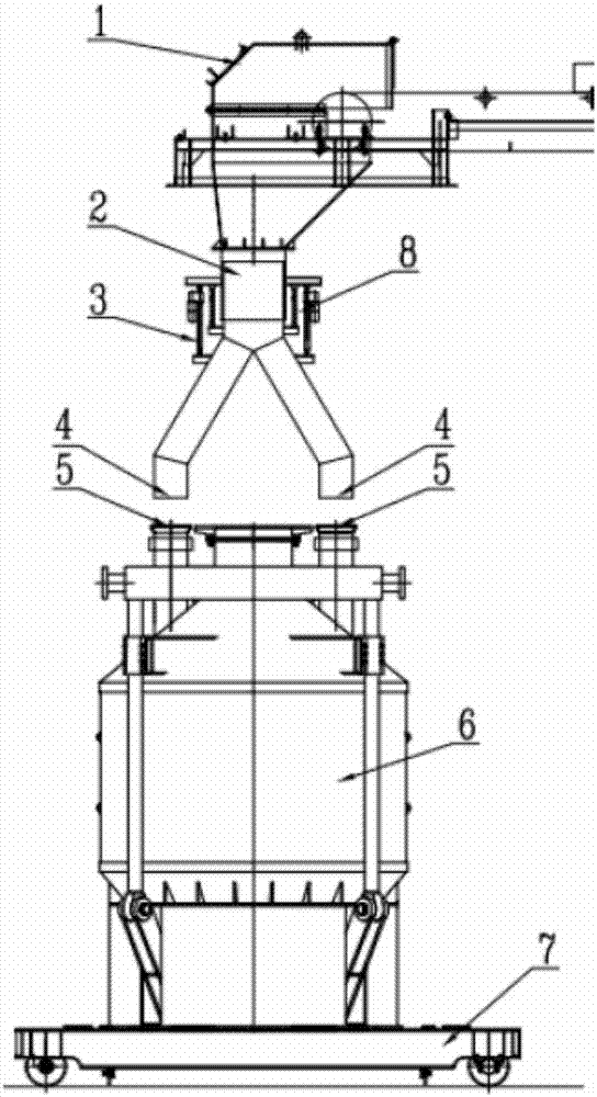
[0026] like figure 2 As shown, the chute situation is when the lifting device is in a normal state (lifting state), and the mobile feeding device 6 moves to a designated position under the lifting chute by the dolly 7, waiting for feeding.
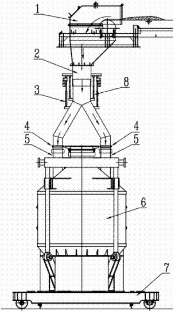
[0027] like image 3 As shown, it is the state of the chute after the lifting device is lowered. After the discharge port 4 of the lifting chute 2 is docked with the feed port 5 of the mobile device 6, feeding is carried out. The material enters the lifting chute 2 through the belt head 1, and the material is dispersed through the lifting chute 2 and enters the two feeding ports 5 of the mobile device 6 to complete the feeding. When the material is added to the designated position of the mobile device 6, the feeding is stopped, the lifting chute 2 rises, and the mobile device 6 moves forward to the next process.
[0028] Features and advantages of the present invention are:
[0029] 1. Space saving. When no material is added, it is nor...
PUM
 Abstract
Description
Claims
Application Information
PatSnap Eureka turns technology decisions into work you can execute. Powered by our Innovation Knowledge Graph, it runs expert workflows across engineering, life sciences, materials and intellectual property. Get your review-ready output in minutes.


