Lifting appliance and method for mounting furnace rollers of annealing furnaces

A technology for annealing furnaces and furnace rolls, which is applied in the field of metal heat treatment equipment, can solve the problems of difficult loading and unloading of furnace rolls, easy equipment injury, and time-consuming problems, and achieves benefits in installation efficiency, adjustment of the axis position of furnace rolls, and safety effect

Active Publication Date: 2015-09-09
CHINA MCC5 GROUP CORP
View PDF5 Cites 1 Cited by
  • Summary
  • Abstract
  • Description
  • Claims
  • Application Information

AI Technical Summary

Problems solved by technology

At the same time, there are generally multiple furnace rollers in the annealing furnace. During the installation and maintenance of the annealing furnace, due to the weight and volume of the furnace rollers, it is usually difficult to load and unload the furnace rollers, time-consuming, and prone to injury or equipment damage. The problem of the accident, the present invention provides a sling for the installation of the annealing furnace roller and the installation method using the sling

Method used


Image

  • Lifting appliance and method for mounting furnace rollers of annealing furnaces
  • Lifting appliance and method for mounting furnace rollers of annealing furnaces

Examples


Embodiment 1

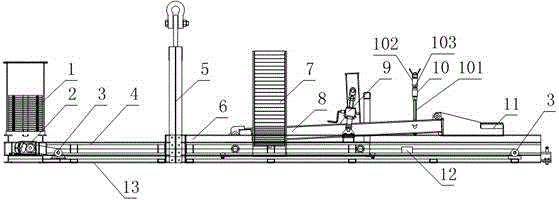
[0032] like figure 1 and figure 2 , a hanger for the installation of annealing furnace rollers, including a strip rail 13 and a moving trolley 6, the moving trolley 6 is arranged on the strip rail 13 and the moving trolley 6 can move along the length direction of the strip rail 13 movement, the moving trolley 6 is also provided with a furnace roller fixing part, and also includes a trolley braking device fixed on the strip rail 13, the trolley braking device is connected with the mobile trolley 6, and the strip rail 13 is also provided with There are counterweights;

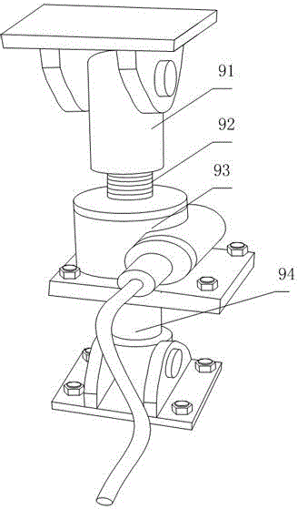
[0033] The furnace roll fixing part includes a lifting platform 8, one end of the lifting platform 8 is hingedly connected with the mobile trolley 6, the other end of the lifting platform 8 is provided with a furnace roller bracket 11, and the lifting platform 8 is also provided with a useful The lifting device 9 that brakes the lifting platform 8 to rotate around the hinge point between itself and the mobile ...

Embodiment 2

[0036] like figure 1 and figure 2 , this embodiment is further defined on the basis of Embodiment 1: as a structural form for adjusting the balance state of the strip rail 13, the counterweight includes a The fixed counterweight 1 and the movable counterweight 7 arranged between the two ends of the strip rail 13. In the above structure, the fixed counterweight 1 and the furnace roller bracket 11 can be respectively arranged at different ends of the strip rail 13, and the movable counterweight 7 is located between the two ends of the strip rail 13. Compared with using a single counterweight Block, the two counterweights can be set lighter respectively, which is convenient for the adjustment of the counterweight in the application process of the present invention.

[0037] As a way to facilitate the adjustment of the respective weights of the fixed counterweight 1 and the movable counterweight 7, the fixed counterweight 1 and the movable counterweight 7 both include a counter...

Embodiment 3

[0039] like figure 1 and figure 2 , this embodiment is further limited on the basis of Embodiment 1: as a structural form with strong movement and driving ability of the braking mobile trolley 6 and high precision of displacement adjustment of the braking mobile trolley 6, the trolley braking device includes an active The sprocket 2 , the driven sprocket 3 and the transmission chain 4 wound on the driving sprocket 2 and the driven sprocket 3 , and the moving trolley 6 is fixed on the transmission chain 4 .

[0040] In order to ensure the stability of the position of the traction force on the transmission chain 4 during the braking process of the trolley braking device as much as possible, and to facilitate the displacement adjustment accuracy of the structure and the compactness of the structure, there are more than one driven sprocket 3, and The driven sprocket 3 is arranged in a row on the bar rail 13 at the same height. Further, after the moving trolley 6 arrives at the r...


PUM


Abstract

The invention discloses a lifting appliance and a method for mounting furnace rollers of annealing furnaces. The lifting appliance comprises a strip-shaped rail, a moving trolley and a trolley brake apparatus. A furnace roller fixing portion is further arranged on the moving trolley, and balancing weights are further arranged on the strip-shaped rail; the furnace roller fixing portion comprises a lifting rack, and a lifting device and a roller neck compressing device are further respectively arranged on the lifting rack. The lifting appliance and the method have the advantages that the lifting appliance is simple in structure, the method is simple in operation, the gravity center position of a combined structure comprising the furnace rollers and the lifting appliance can be adjusted, accordingly, the axes of the furnace rollers can be advantageously repositioned, and the lifting appliance and the method are favorable for the hoisting safety; owing to structural characteristics of the lifting appliance, the furnace rollers can stably move by the aid of the lifting appliance under the matching effects of functions of upper components of the lifting appliance under the condition that lifting ropes are inconvenient to cross furnace shells, accordingly, the furnace rollers can be accurately fed into mounting positions, and the lifting furnace and the method are favorable for furnace roller mounting convenience.

Description

technical field [0001] The invention relates to the field of metal heat treatment equipment, in particular to a suspender for installing rollers in an annealing furnace and an installation method using the suspender. Background technique [0002] In the heat treatment method of metal materials, the metal heat treatment process in which the metal is slowly heated to a certain temperature, kept for a sufficient time, and then cooled at an appropriate speed is called annealing. The purpose of annealing is to make the material or workpiece soft after casting, forging, welding or cutting, improve the shape and toughness of the material or workpiece, homogenize the chemical composition of the material or workpiece, eliminate residual stress, and obtain the desired effect. Material physical properties. Annealing in the prior art has been refined to include recrystallization annealing, isothermal annealing, homogenization annealing, spheroidizing annealing, stress relief annealing,...

Claims


Application Information

Patent Timeline
Patent Type & Authority Applications(China)
IPC IPC(8): C21D1/26
Inventor 贾贵军潘贞君李茂林
Owner CHINA MCC5 GROUP CORP
Why Eureka
Try Eureka