Cable take-up device

A wire take-up device and cable wire technology, applied in the field of cables, can solve the problems of cluttered cable withdrawal, and achieve the effects of saving materials, reducing costs, and balancing movement

Pending Publication Date: 2018-05-01
重庆华旗线缆有限公司
View PDF6 Cites 4 Cited by
  • Summary
  • Abstract
  • Description
  • Claims
  • Application Information

AI Technical Summary

Problems solved by technology

[0004] Aiming at the deficiencies in the prior art, the present invention provides a cable take-up device, which solves the problem that when the traditional reel collects the cable, the reel reverses and the cable exit becomes messy

Method used


Image

  • Cable take-up device
  • Cable take-up device
  • Cable take-up device

Examples


Embodiment Construction

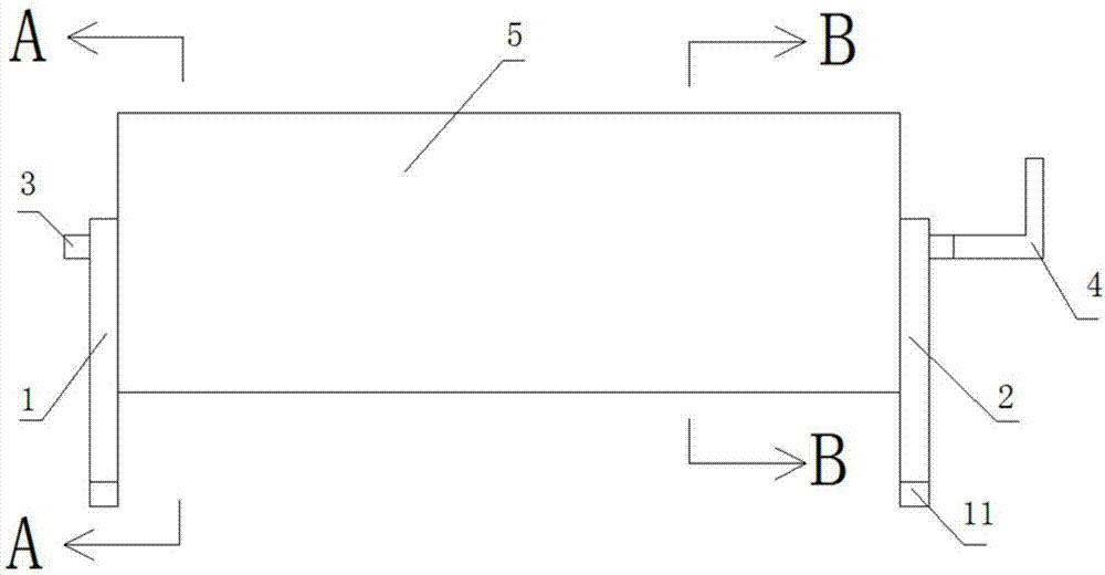
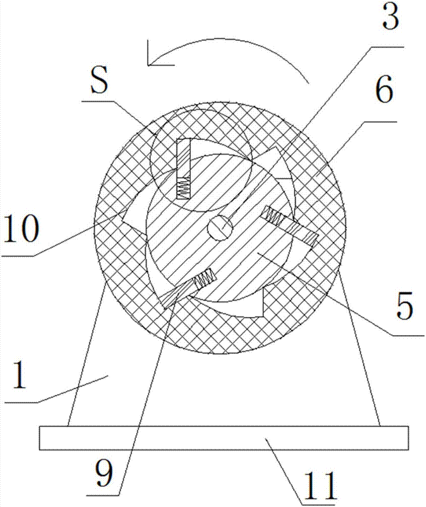
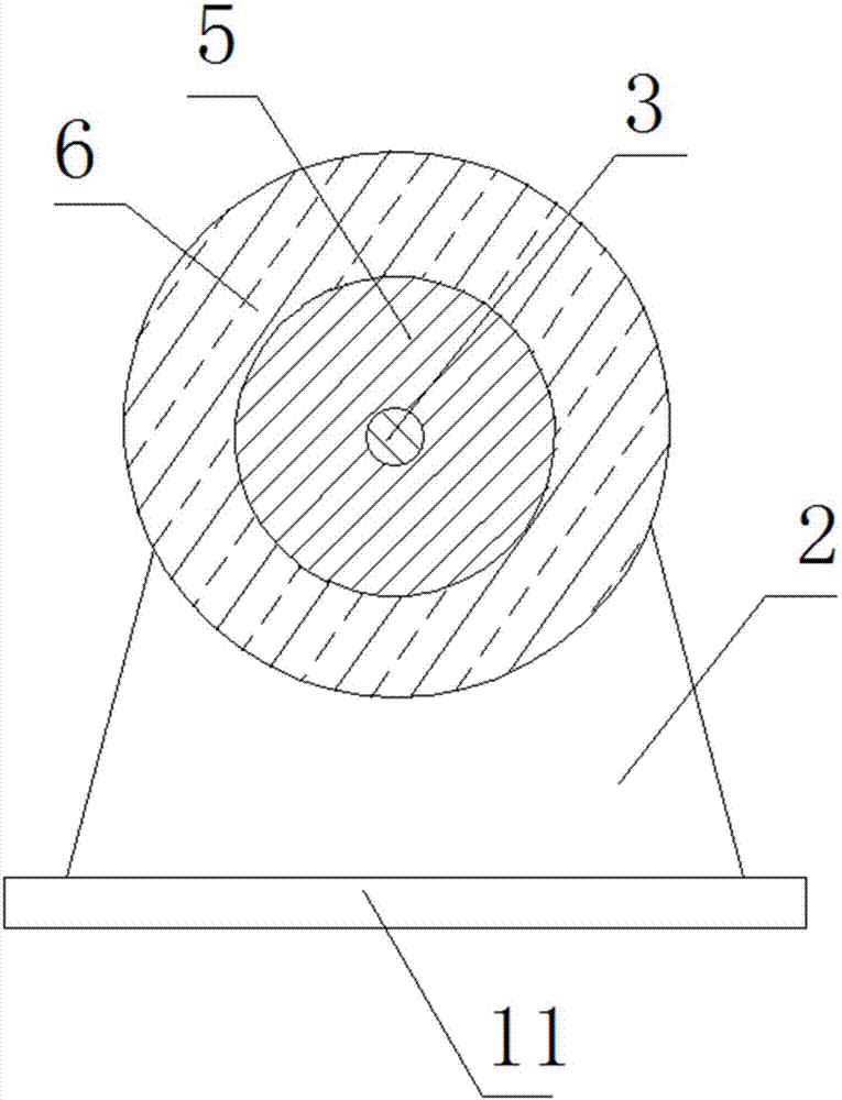
[0026] The present invention will be further described below in conjunction with the accompanying drawings. Such as Figure 1-4 As shown, a cable take-up device includes a first riser 1 and a second riser 2 oppositely arranged, the cross-sections of the first riser 1 and the second riser 2 are both isosceles trapezoidal, Both the lower bottom of the first vertical board 1 and the lower bottom of the second vertical board 2 are connected to the base 11 .

[0027] A rotating shaft 3 is installed between the first vertical plate 1 and the second vertical plate 2, and a power device 4 connected to the rotating shaft 3 is provided on the outside of the second vertical plate 2, see figure 1 , that is, one end of the rotating shaft 3 is connected to the first vertical plate 1 in rotation, and the other end of the rotating shaft 3 passes through the second vertical plate 2 and is connected to the power unit 4 on the outside of the second vertical plate 2. In this embodiment, the powe...


PUM


Abstract

The invention provides a cable take-up device. The cable take-up device comprises a first vertical plate and a second vertical plate which are arranged oppositely; a rotating shaft is rotatably arranged between the first vertical plate and the second vertical plate; a power device connected with the rotating shaft is arranged on the outer side of the second vertical plate; a rotating cylinder rotating along with the rotating shaft is arranged outside the rotating shaft in a sleeving way; a winding reel is rotatably arranged outside the rotating cylinder in a sleeving way; three guide grooves are distributed on the outer wall of the rotating cylinder on the first vertical plate side circumferentially and uniformly; springs and pawls are arranged in the guide grooves; one end of each springis connected with the bottom wall of each guide groove and the other end of the spring is connected with the pawl; six inner ratchet wheels matched with the pawls are arranged in the winding reel; andone end of each pawl is fixedly connected with the spring and the other end of the pawl extends into each inner ratchet wheel and is matched with the inner ratchet wheel. The cable take-up device canguarantee the tidy winding effect of the cable during forward rotation winding and also can prevent reversed rotation of the winding reel and guarantee that winding is not returned, and the cost is controlled.

Description

technical field [0001] The invention relates to the technical field of cables, in particular to a cable take-up device. Background technique [0002] A cable is made of one or more mutually insulated conductors and an outer insulating protective layer. It is a wire that transmits power or information from one place to another. The traditional outer insulating protective layer is mostly made of rubber. [0003] When the traditional cables are collected and organized, they will be sorted by the wire take-up device. The wire take-up device is generally a winding drum, which fixes one end of the cable to the winding drum, and then turns the winding drum to wind the cable onto the winding drum. However, After collecting in this way, if the bobbin is not fixed and the bobbin is reversed, the wound cable will exit with the reversed bobbin and become messy, and the previous collection and arrangement work becomes Pointless and a huge waste of time. Contents of the invention [0...

Claims


Application Information

Patent Timeline
Patent Type & Authority Applications(China)
IPC IPC(8): B65H54/44B65H54/553B65H75/18
CPCB65H54/44B65H54/553B65H75/18B65H2701/34B65H2701/50
Inventor 沈志宗邓帅黄雄波
Owner 重庆华旗线缆有限公司
Why Eureka
Try Eureka