Automatic cable rolling mechanism for new energy automobile charging pile

A new energy vehicle and winding mechanism technology, applied in the direction of electric vehicle charging technology, charging stations, electric vehicles, etc., can solve the problems of excessive space occupation, loose cable winding, knotting, etc., and achieve low processing accuracy, The effect of compact cable winding and low cost

Inactive Publication Date: 2018-05-04
安徽匠桥财务咨询服务有限公司
View PDF7 Cites 3 Cited by
  • Summary
  • Abstract
  • Description
  • Claims
  • Application Information

AI Technical Summary

Problems solved by technology

[0003] An existing cable automatic winding mechanism for a charging pile (application number 201620543222.2) discloses an automatic winding mechanism, including a charging device, the charging device is connected to a charging gun through a cable, and the charging device is provided with a device for placing The gun seat of the charging gun, the charging device is provided with a mounting slot, and a reel for winding the cable is rotatably installed in the mounting slot; it also includes a drive assembly, which includes a drive control module and a drive control module. The driving device and the braking device, the driving control module acts on the driving device so that the driving device drives the reel to rotate, and the driving control module acts on the braking device so that the braking device brakes the reel to rotate; although this winding mechanism To a certain extent, the automatic cable winding operation can be realized, but because the winding mechanism is too simple, it is easy to cause problems such as loose winding of the cable, knotting, taking up too much space, and difficult storage when performing the winding operation.

Method used


Image

  • Automatic cable rolling mechanism for new energy automobile charging pile
  • Automatic cable rolling mechanism for new energy automobile charging pile
  • Automatic cable rolling mechanism for new energy automobile charging pile

Examples


Embodiment

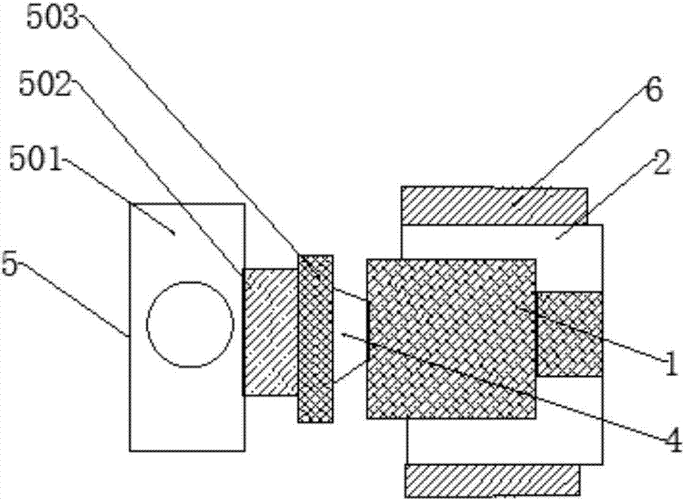
[0028] Such as figure 1 and Figure 4 As shown, the present invention provides a cable automatic winding mechanism for a new energy vehicle charging pile, including a winding shaft 1, the outer surface of the winding shaft 1 is sleeved with a bobbin 2, and the winding bobbin 2 A winding groove 3 is dug on the surface, and the inner diameter of the winding groove 3 is consistent with the outer diameter of the cable to be wound; the end of the reel of the winding shaft 1 is sleeved with a coupling gear 4, and The other end is sleeved with a two-way transmission mechanism 5; the rewinding shaft 1 is connected to the two-way transmission mechanism 5 through the coupling gear 4. When the two-way transmission mechanism 5 starts to work, it drives the rewinding shaft 1 to rotate, and the cable is connected with the rotation when rotating. The cable is clamped inside the winding groove 3, so as to realize the automatic winding operation of the cable.

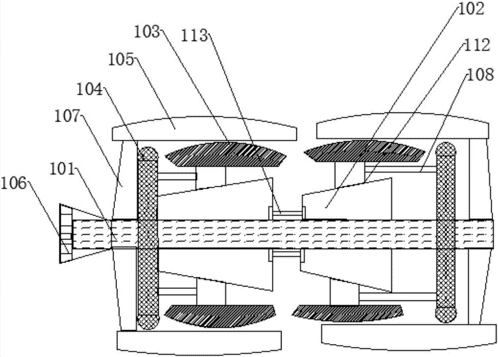
[0029] Such as figure 2 As s...


PUM


Abstract

The invention discloses an automatic cable rolling mechanism for a new energy automobile charging pile. The automatic cable rolling mechanism comprises a rolling shaft. The outer surface of the rolling shaft is in cup joint with a winding barrel. A winding groove is chiseled in the surface of the winding barrel. The tail end of a reel of the rolling shaft is in cup joint with a coupling gear, andthe other end of the coupling gear is in cup joint with a both-way transmission mechanism. The rolling shaft comprises a main shaft, the front end part of the main shaft is in cup joint with inner conical sleeves at equal intervals, and the outer surfaces of the inner conical sleeves are provided with arc small bulging tiles. The parts, at the two ends of the inner conical sleeves, of the main shaft are in cup joint with supporting discs. The parts between the supporting discs and the small bulging tiles are in cup joint with large bulging tiles. The tail end of the main shaft is further in cup joint with a bevel gear. The both-way transmission mechanism comprises a drive motor, an output shaft of the drive motor is in cup joint with an output flange, the other end of the output flange isin cup joint with a driving wheel disc, and the driving wheel disc is in cup joint with the tail end of the rolling shaft through a driving chain. By means of the automatic cable rolling mechanism, automatic automobile charging pile cable rolling operation can be rapidly achieved, the winding efficiency is high, and the wound cable is twisted tidily and tightly without loosening.

Description

technical field [0001] The invention relates to the field of charging pile devices, in particular to a cable automatic winding mechanism for a new energy vehicle charging pile. Background technique [0002] New energy vehicles refer to the use of unconventional vehicle fuels as power sources (or the use of conventional vehicle fuels, the use of new vehicle power devices), integrated vehicle power control and advanced technology in driving, the formation of advanced technical principles, with Automobiles with new technology and new structure. At present, the most common use of new energy vehicles is electric power. Because the consumption of electric energy is generally large, many car charging piles have been installed in some cities. The function of the charging pile is similar to the refueling machine in the gas station. It can be fixed on the ground or wall, and installed in public buildings (public buildings, shopping malls, public parking lots, etc.) and residential ar...

Claims


Application Information

Patent Timeline
Patent Type & Authority Applications(China)
IPC IPC(8): B65H75/44B65H75/48B60L11/18
CPCB60L53/31B65H75/44B65H75/4486B65H75/48B65H2701/34Y02T10/70Y02T10/7072Y02T90/12
Inventor 王露露
Owner 安徽匠桥财务咨询服务有限公司
Why Eureka
Try Eureka