Pole stay wire connector binding device and method for electrical engineering installation

A technology for pole pulling and power engineering, which is applied in the processing of building materials, building types, buildings, etc., can solve the problems of high labor intensity, easy damage to tools, and easy damage to the galvanized layer of the wire, so as to achieve high efficiency. Improve, reduce labor intensity, improve the effect of binding quality

Active Publication Date: 2018-07-27
HEFEI HONGGUANG ELECTRIC CO LTD
View PDF5 Cites 2 Cited by
  • Summary
  • Abstract
  • Description
  • Claims
  • Application Information

AI Technical Summary

Problems solved by technology

[0003] The purpose of the present invention is to overcome the deficiencies of the prior art, and the purpose is to provide a pole cable joint binding device and method for electric power engineering installation, which solves the problems of high labor intensity, easy damage of tools, and plating of the cable when binding the cable. The zinc layer is easily damaged; it is difficult for new employees to master the technical requirements of binding and pulling wires

Method used


Image

  • Pole stay wire connector binding device and method for electrical engineering installation
  • Pole stay wire connector binding device and method for electrical engineering installation
  • Pole stay wire connector binding device and method for electrical engineering installation

Examples


Embodiment 1

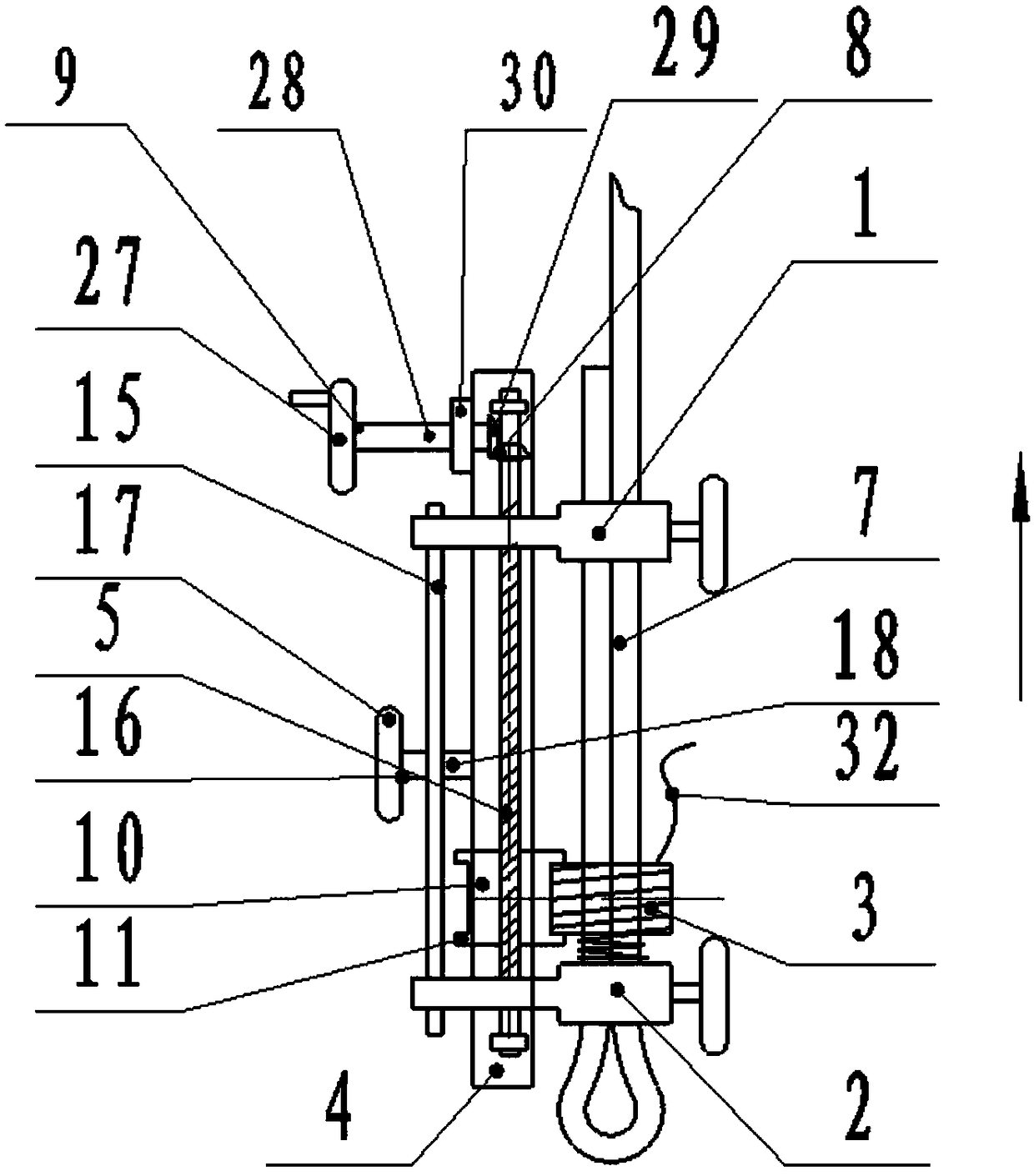
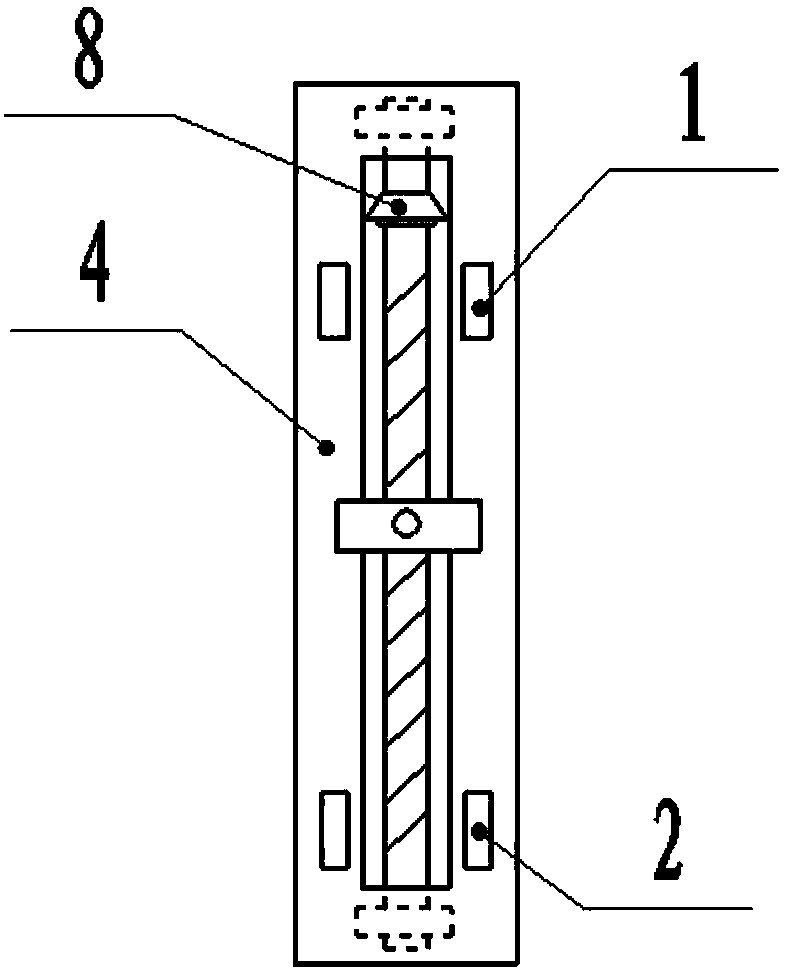
[0037] Such as Figure 1-6 As shown, the present invention is a kind of electric pole guy wire joint binding device that is used for electric power engineering installation, comprises the first guy wire joint clamping part 1, the second guy wire joint clamping part 2, the wire binding device 3, the binding frame plate 4 and The transmission screw rod 5, the front ends of the first cable joint clamping part 1 and the second cable joint clamping part 2 are correspondingly inserted at the two ends of the binding frame plate 4, and the binding frame plate 4 and the cable are arranged parallel to each other during installation. , the binding frame plate 4 adjusts the distance between the transmission screw 5 and the binding wire binding device 3 by sliding on the front ends of the first cable joint clamping part 1 and the second cable joint clamping part 2, and the first cable joint clamps The rear ends of the part 1 and the second cable joint clamping part 2 are clamped on both en...


PUM


Abstract

The invention discloses a pole stay wire connector binding device and method for electrical engineering installation. The pole stay wire connector binding device comprises a first stay wire connectorclamping element, a second stay wire connector clamping element, a tying binding machine, a binding frame plate and a transmission lead screw. The front ends of the first stay wire connector clampingelement and the second stay wire connector clamping element are correspondingly inserted into two end portions of the binding frame plate, and the rear ends of the first stay wire connector clamping element and the second stay wire connector clamping element are clamped on two ends of the parts which needs to be bound of stay wire connectors by arranging clamping structures. The transmission leadscrew is arranged on the binding frame pate, a lead screw umbrella-shaped tooth is arranged at the upper end of the transmission lead screw, and a binding hand wheel device which is matched with leadscrew umbrella-shaped tooth and used for controlling the rotation of the transmission lead screw is arranged; and the tying binding machine can be rotated and moved forwards and backwards through simple operation, and stay wire binding can be easily completed. Compared with manual binding, the efficiency is increased by more than 5 times, the labor intensity is reduced, and the binding quality isimproved.

Description

technical field [0001] The invention relates to the technical field of electric power engineering construction, in particular to a device and method for binding cable joints of electric poles for electric power engineering installation. Background technique [0002] Now, on the poles (such as terminal poles and corner poles) of high and low voltage power supply lines, pull wires are generally used to prevent the poles from tilting, and the lower ends of the binding pull wires are often alternately used. (When tying the lower end of the pull wire, the lower end of the pull wire must be used to form a double-strand wire through the UT wire clip first, and then the double-strand wire is bound). The binding material of the pull wire is often galvanized iron wire (commonly known as tie wire). There are following defects when adopting above-mentioned tool binding backguy: 1, labor intensity is big; Contents of the invention [0003] The purpose of the present invention is to ov...

Claims


Application Information

Patent Timeline
IPC IPC(8): E04H12/20E04G21/14E04G21/16
Inventor 杨佳志
Owner HEFEI HONGGUANG ELECTRIC CO LTD
Why Eureka
Try Eureka