On-table rapid-installation and rapid-disassembly apparatus for faucet

A fast-installation and faucet technology, applied in the field of faucets, can solve the problems of inability to move up and down in the axial direction, cannot reach, affect the clamping force and stability, etc., and achieve the effect of simple and convenient installation process, easy disassembly process, and reduced occupancy

Pending Publication Date: 2018-05-01
XIAMEN SOLEX HIGH TECH IND CO LTD
View PDF9 Cites 6 Cited by
  • Summary
  • Abstract
  • Description
  • Claims
  • Application Information

AI Technical Summary

Problems solved by technology

[0007] However, there is no limiting structure disclosed under the above-mentioned fixed base to prevent the clamping block from rotating when the clamping bolt rotates, so that the clamping block easily rotates with the clamping bolt and cannot be axially displaced up and down to perform the clamping action , so it may still be necessary to fix the clamping block from the bottom of the cleaning table during operation, but it cannot achieve the effect of clamping the fixed base by completely rotating from the bottom of the cleaning table
On the other hand, the above two clamping blocks are also prone to misalignment, and cannot be accurately controlled to be symmetrical to each other, and at the same time completely clamp and fit the position below the cleaning table, which affects the clamping force and stability

Method used


Image

  • On-table rapid-installation and rapid-disassembly apparatus for faucet
  • On-table rapid-installation and rapid-disassembly apparatus for faucet
  • On-table rapid-installation and rapid-disassembly apparatus for faucet

Examples


Embodiment Construction

[0038] The present invention will be further described below through the accompanying drawings and specific embodiments.

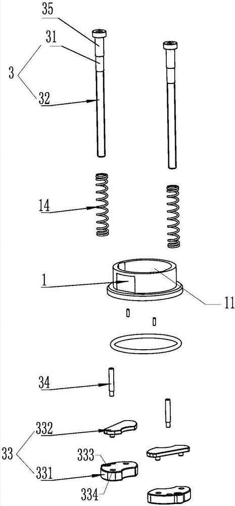
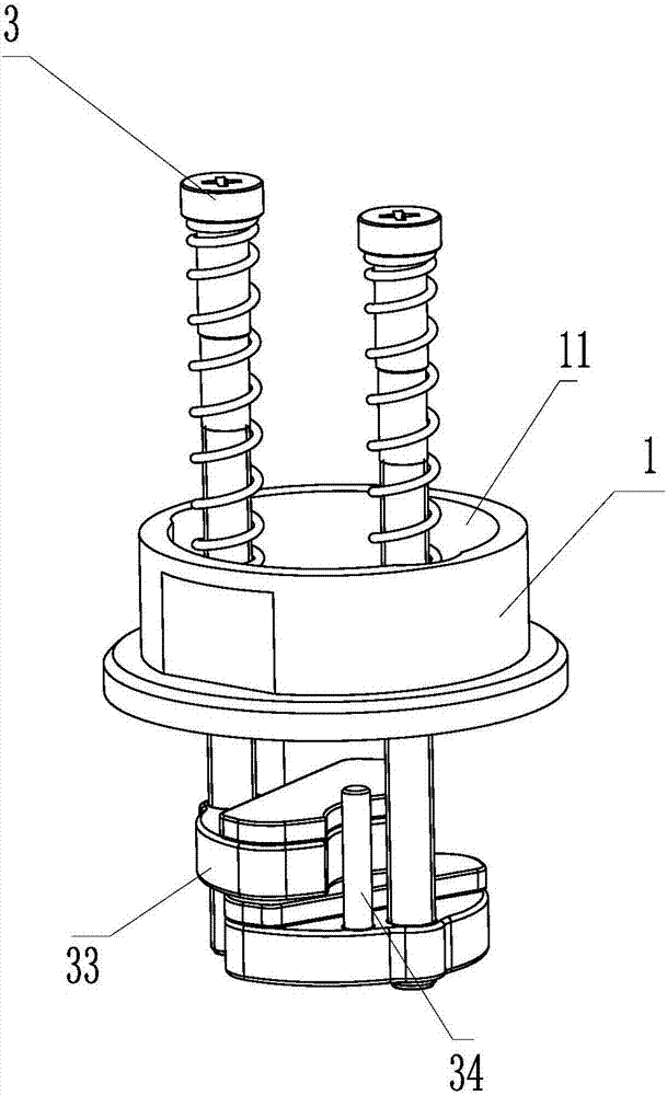
[0039] refer to Figure 1-14 , a platform quick-installation and quick-release device for faucets, comprising:

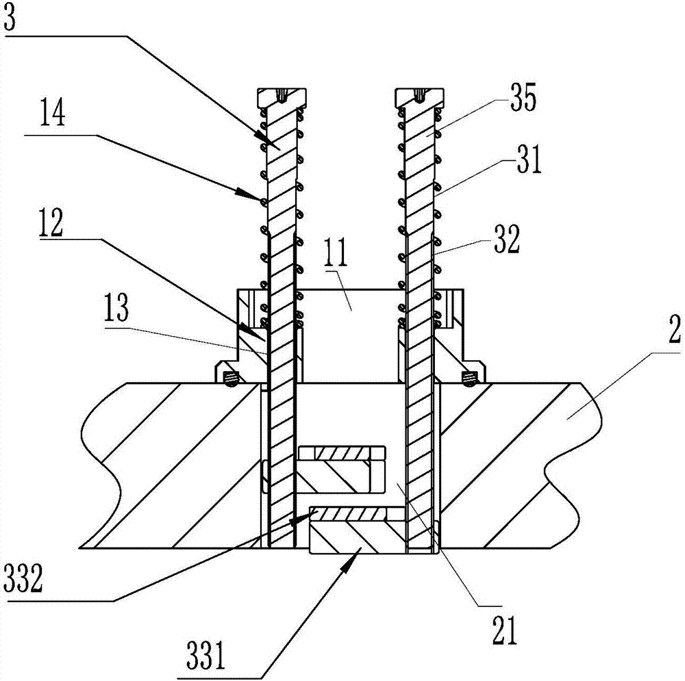
[0040] The base 1 is placed on the upper surface of the table 2 and has a hole 11 connected to the mounting hole 21 of the table;

[0041]The pressure rod, preferably a stepped bolt 3 in this embodiment, has a threaded section 32, a guide section 31 and a limiting section 35, the diameter of the threaded section 32 is smaller than the diameter of the guiding section 31, and the diameter of the guiding section 31 is smaller than the limiting section. The diameter of bit segment 35. The side wall of the hole 11 extends a boss 12 into the hole, and the boss 12 has a relief hole along the length direction of the hole 11. In this embodiment, the relief hole is a screw hole 13; the stepped bolt One end of 3 is inserted into the screw hole 13 and ex...


PUM


Abstract

The invention provides an on-table rapid-installation and rapid-disassembly apparatus for a faucet. The on-table rapid-installation and rapid-disassembly apparatus comprises a base arranged on the upper surface of a table surface and provided with a hole communicated to a table surface installation hole, wherein the side wall of the hole extends into the hole to form a boss, the boss is provided with a position reserving hole along the length direction of the hole, one end of a pressing rod is inserted into the position reserving hole and extends into the installation hole, the other end of the pressing rod is exposed outside the hole, an elastic reset member is arranged between the other end of the pressing rod and the position reserving hole, and the pressing rod end extending into the installation hole is provided with an ejection against member rotating coaxial to the pressing rod and a position limiting member. According to the present invention, when external force is applied onthe pressing rod end exposed outside the hole, the pressing rod moves to a second position from a first position along the length direction of the hole; when the pressing rod is positioned at the second position, the ejection against member moves out of the installation hole, and the position limiting member is positioned in the installation hole; the pressing rod rotates to make the ejection against member rotates to the position below the lower surface of the table surface, and the position limiting and the installation hole eject against; and the external force is removed, and the elastic reset member drives the pressing rod to upward move, such that the ejection against member and the lower surface of the table surface eject against.

Description

technical field [0001] The invention relates to a faucet, in particular to a quick-installation and quick-disassembly device for a faucet. Background technique [0002] Existing faucets, especially those installed on the countertop of the kitchen sink, are often equipped with a pull-out nozzle, which is convenient for users to pull out and clean in the sink, such as cleaning pots, plates, etc. The functions and advantages of cleaning from below are widely known to consumers, so I won’t repeat them here. [0003] The single handle pull-out faucet can be used on sink tops with either three mounting holes or a single mounting hole. The single-handle pull-out faucet only needs to control the water through a single handle, and it is easier and faster to operate than the double-handle pull-out faucet. [0004] It should be noted that the single-handle pull-out faucet is mainly provided with an externally threaded seat tube at the bottom of the faucet body to pass through the ins...

Claims


Application Information

Patent Timeline
Patent Type & Authority Applications(China)
IPC IPC(8): E03C1/04
CPCE03C1/04E03C1/0401
Inventor 穆炜海洪春姐陈文兴王明南
Owner XIAMEN SOLEX HIGH TECH IND CO LTD
Why Eureka
Try Eureka