Cooling device for industrial reaction furnace

A technology of cooling device and industrial reaction, applied in the direction of furnace cooling device, etc., can solve the problems of large amount of cooling liquid, long cooling time, poor cooling effect of reactants, etc., and achieve the effect of high use efficiency

Active Publication Date: 2018-05-01
江苏兰蒂斯生物质复合材料研究院有限公司
View PDF4 Cites 0 Cited by
  • Summary
  • Abstract
  • Description
  • Claims
  • Application Information

AI Technical Summary

Problems solved by technology

[0003] In the prior art, most of the cooling furnace devices in the reaction furnace place the reactants in the cooling furnace, and take away the heat through water-cooled heat exchange. However, the cooling furnace itself loaded with reactants is still, and the reactants in the middle of the furnace are actually poor cooling
At the same time, in the related art, the cooling furnace is mostly water-cooled to cool down, and the cooling liquid is used in large quantities and stays on the outer wall of the furnace for a short time, resulting in a large amount of cooling liquid used but a long cooling time and low cooling efficiency.

Method used


Image

  • Cooling device for industrial reaction furnace

Examples


Embodiment Construction

[0016] The present invention will be further described below in conjunction with the accompanying drawings and specific embodiments.

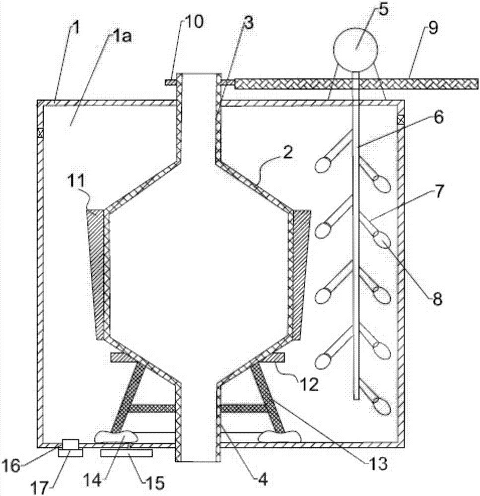
[0017] Please refer to the attached figure 1 As shown, the present invention provides a cooling device for an industrial reaction furnace, comprising an outer furnace body 1 with a cooling chamber 1a, a cooling furnace body 2 is arranged in the cooling chamber 1a, and the top of the cooling furnace body 2 passes through an upper through pipe 3. The outer furnace body 1 communicates with the outside, and the bottom of the cooling furnace body 2 passes through the outer furnace body 1 to communicate with the outside through the lower through pipe 4; a motor 5 is arranged on the top outer wall of the outer furnace body 1, and a motor 5 is arranged in the cooling chamber 1a. The rotating rod 6 driven by the motor 5 is arranged near the outer wall of the cooling furnace body 2, and the extending direction of the rotating rod 6 is consistent with the...


PUM


Abstract

The invention discloses a cooling device for an industrial reaction furnace. The cooling device comprises an outer furnace body with a cooling cavity, a cooling furnace body is arranged in the coolingcavity, the top of the cooling furnace body communicates with the outside through an upper through pipe penetrating through the outer furnace body, and the bottom of the cooling furnace body communicates with the outside through a lower through pipe penetrating through the outer furnace body; a motor is arranged on the outer side wall of the top of the outer furnace body, and a rotating rod driven by the motor is arranged in the cooling cavity, is arranged close to the outer side wall of the cooling furnace body, and is sequentially provided with fixing rods extending obliquely downwards at equal intervals; rod heads of the fixing rods are hinged to flow diffusing blades vertically swung, the rotating rod and the fixing rods are correspondingly provided with flow diffusing grooves communicating with one another, and a flow guide pipe externally connected with a cooling liquid is installed on the flow diffusing grooves; the end, close to the motor, of the rotating rod is coaxially andfixedly provided with a first gear, and a second gear meshed with the first gear is coaxially and fixedly arranged at the upper end of the upper through pipe; and an absorbent cotton cylinder is adhered to the outer side wall of the middle of the cooling furnace body, and the thickness of the absorbent cotton cylinder is gradually reduced from top to bottom.

Description

technical field [0001] The invention relates to the technical field of industrial reaction furnaces, in particular to a cooling device for industrial reaction furnaces. Background technique [0002] There are various forms of industrial reaction furnaces. In actual use, the temperature in the reaction furnace changes frequently, and it is often necessary to cool down the furnace body of the reaction furnace. [0003] In the prior art, most of the cooling furnace devices in the reaction furnace place the reactants in the cooling furnace, and take away the heat through water-cooled heat exchange. However, the cooling furnace itself loaded with reactants is still, and the reactants in the middle of the furnace are actually The cooling effect is not good. At the same time, in the related art, most of the cooling furnaces are cooled by water, and a large amount of cooling liquid is used to stay on the outer wall of the furnace for a short period of time, resulting in a large amo...

Claims


Application Information

Patent Timeline
IPC IPC(8): F27D1/12
CPCF27D1/12
Inventor 李洪毅
Owner 江苏兰蒂斯生物质复合材料研究院有限公司
Why Eureka
Try Eureka