Judgment method of switch position of high-voltage direct-current control protection system

A control and protection, high-voltage DC technology, applied in measuring devices, circuit breaker testing, instruments, etc., to avoid misjudgment

Active Publication Date: 2018-05-01
国网河南省电力公司超高压公司 +1
View PDF9 Cites 1 Cited by
  • Summary
  • Abstract
  • Description
  • Claims
  • Application Information

AI Technical Summary

Problems solved by technology

[0006] In view of this, the object of the present invention is to address the deficiencies of the prior art and provide a method for judging the position of a switch in a high-voltage direct current control and protection system. Operation to accurately judge the real position of the circuit breaker. When the minute signal and the closing signal are consistent, the minute position output a

Method used


Image

  • Judgment method of switch position of high-voltage direct-current control protection system
  • Judgment method of switch position of high-voltage direct-current control protection system
  • Judgment method of switch position of high-voltage direct-current control protection system

Examples


Embodiment 1

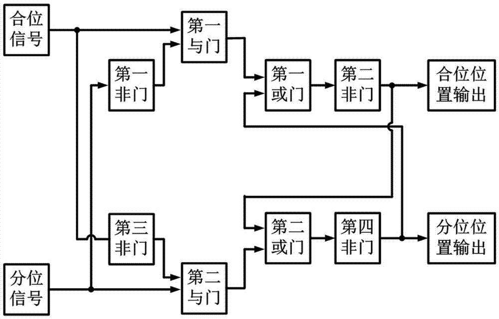
[0025] Such as image 3 As shown, a method for judging the switch position of a high-voltage direct current control and protection system includes the following steps:

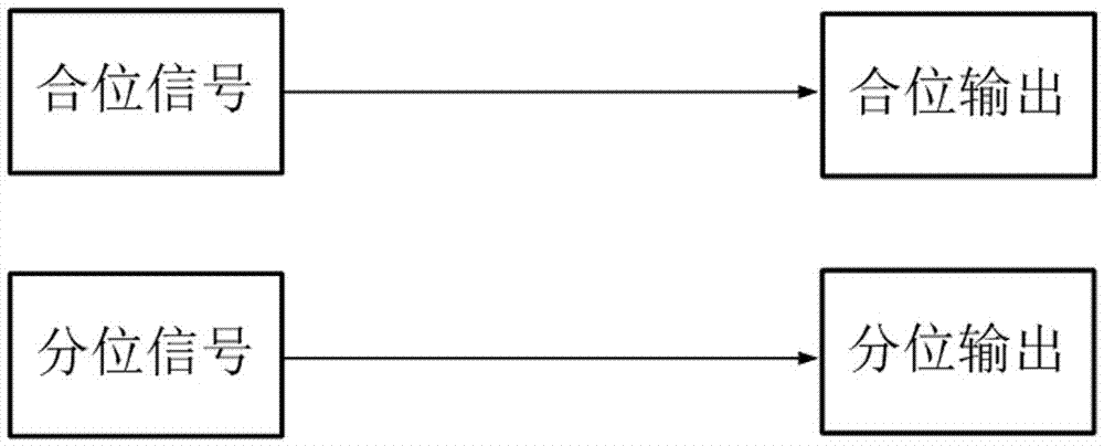
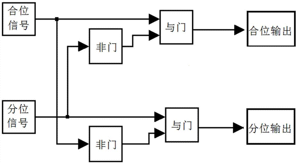
[0026] Step 1. The closing signal and the dividing signal of a single switch in the high-voltage direct current control and protection system are used as two input signals at the same time. When there is an input signal, it is represented as 1, and when there is no input signal, it is represented as 0.

[0027] Step 2. Pass the combination signal and the fractional signal through the first NOT gate through the first AND gate, and then pass the output signal of the first AND gate and the fractional position output through the first OR gate and the second NOT gate for logic After the operation, its outlet is output as the combined position.

[0028] Step 3. Pass the dividing signal and the closing signal through the third NOT gate through the second AND gate, and then pass the output signal of the second AND ga...

Embodiment 2

[0035] The difference between it and Embodiment 1 is that in the step 5, when the closing signal input is 1 and the dividing signal input is 0, the closing position output is 1 and the dividing position output is 0, indicating that the high-voltage direct current The switch in the control and protection system is in the closed state, and there is no loss of the minute signal.

Embodiment 3

[0037] The difference between it and Embodiment 2 is that: in the step 5, when the closing signal input is 0 and the dividing signal input is 1, the closing position output is 0, and the dividing position output is 1, indicating that the high-voltage direct current The switch in the control and protection system is in the off state, and there is no loss of closing signal.


PUM


Abstract

The invention discloses a judgment method of a switch position of a high-voltage direct-current control protection system. The method comprises steps of firstly, using a closing signal and an openingsignal of a single switch as two input signals; allowing the closing signal and the opening signal passing through a first Not gate to pass a first AND gate, outputting and allowing an output signal and a closing position of the first AND gate to be subjected to logic operation successively, and using the exit thereof as the closing position for output; allowing the opening signal and a closing signal of a third NOT gate to pass through the second AND gate, outputting and allowing an output signal and the closing position of the second AND gate to be subjected to logic operation successively and using the exit thereof as the opening position for output; and when the input of the closing signal and the opening signal is 0, representing that there is a signal loss phenomenon and keeping theoutput of the closing position and the opening signal to be the states before the signal loss. According to the invention, problems of mistaken judgment and mistaken operation of the protection systemcaused by faults of a single element of a signal loop can be effectively avoided.

Description

technical field [0001] The invention belongs to the technical field of high-voltage direct current transmission engineering, and in particular relates to a method for judging switch positions of a high-voltage direct current control and protection system. Background technique [0002] In the high-voltage DC control and protection system, the operation mode of the DC equipment is judged according to the position of the switch (knife switch), and the protection mode and protection setting value of the DC equipment are determined according to the operation mode. When the position of the switch (knife switch) is inconsistent with the actual situation, the protection will malfunction Or refuse to move. The position signal of the switch (knife switch) is judged by accessing the position signal or close signal of the control protection system. Under normal circumstances, only one of the position signal and close signal should exist. The common switch (knife switch) position judgme...

Claims


Application Information

Patent Timeline
IPC IPC(8): G01R31/327
CPCG01R31/3271
Inventor 连进灿张嘉涛闰兴龙陈炳华吕拦坡刘岳王默薛飞刘怡荆扬杨军景王群锋刘天祥武作斌
Owner 国网河南省电力公司超高压公司
Why Eureka
Try Eureka