Relay service life detection device

A detection device and relay technology, which is applied in measurement devices, circuit breaker testing, instruments, etc., can solve the problem of MCU powerlessness and other problems, and achieve the effect of ensuring accuracy

Active Publication Date: 2018-05-01
邳州市铁富九龙公共服务有限公司
View PDF4 Cites 8 Cited by
  • Summary
  • Abstract
  • Description
  • Claims
  • Application Information

AI Technical Summary

Problems solved by technology

Use the MCU software delay method to remove the influence of the jitter pulse. When the MCU needs to perform life tests on multiple relay switches at the same time, the MCU software delay method will make the MCU unable to do what it wants.

Method used


Image

  • Relay service life detection device
  • Relay service life detection device
  • Relay service life detection device

Examples


Embodiment Construction

[0031] The present invention will be further described below in conjunction with accompanying drawing.

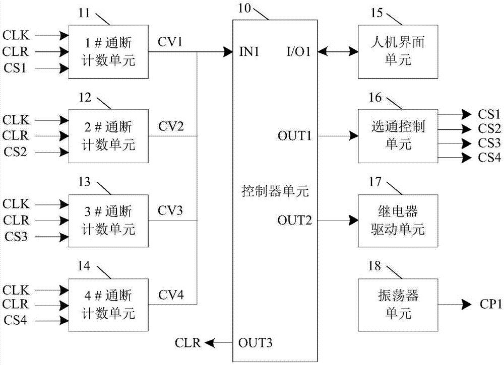
[0032] figure 1 It is a block diagram of an embodiment of a relay life detection device when L=4, including a controller unit 10, a 1# on-off counting unit 11, a 2# on-off counting unit 12, a 3# on-off counting unit 13, and a 4# on-off counting unit 14 , a man-machine interface unit 15 , a gating control unit 16 , a relay drive unit 17 , and an oscillator unit 18 .

[0033] The man-machine interface unit 15 communicates with the controller unit 10 through the interface I / O1 of the controller unit 10, and is used to detect the issuing of commands, parameter modification, and the display of the life of each relay switch; the controller unit 10 communicates with the relay through the output port OUT2. The drive unit 17 sends a relay drive signal to control the on-off of the 1# to 4# relay switch; the oscillator unit 18 outputs the sampling clock pulse CP1 to the 1# on-off cou...


PUM


Abstract

A relay service life detection device includes a controller unit, L on-off counting units, a human-machine interface unit, a relay drive unit, and an oscillator unit, and can simultaneously count thenumber of on-off times of a plurality of relay switches to obtain on-off count values and determine whether the relay and the switch thereof are faulted according to the on-off count values. Anti-pulse interference circuits in the on-off counting units can filter out the edge jitter interference and narrow pulse interference in count pulses, and ensure the accuracy of relay service life detection.Multiple counters are disposed outside the controller unit to count the number of on-off times of the relay switches. The number of relay switches that detect the service life of the relay is not limited by the number of counters in the controller unit.

Description

technical field [0001] The invention relates to the field of testing methods and devices, in particular to a relay life detection device. Background technique [0002] The life of the relay is generally tens of thousands to hundreds of thousands of times. Simulate the use conditions of the relay, by controlling the action of the relay to make the switch on and off to generate electric pulses, and then counting the electric pulses, the life of the relay can be tested. The electric pulse generated by the action of the relay contains edge jitter, and counting the unprocessed pulse directly will cause a huge error. Use the MCU software delay method to remove the influence of the jitter pulse. When the MCU needs to perform life tests on multiple relay switches at the same time, the MCU software delay method will make the MCU unable to do what it wants. Contents of the invention [0003] In order to solve the above problems, the present invention provides a relay life detectio...

Claims


Application Information

Patent Timeline
IPC IPC(8): G01R31/327
CPCG01R31/3278
Inventor 凌云文定都王兵罗学明
Owner 邳州市铁富九龙公共服务有限公司
Why Eureka
Try Eureka