Electromagnetic repulsion mechanism built through angle steel

A technology of electromagnetic repulsion and repulsion mechanism, applied in the direction of circuits, electric switches, electrical components, etc., can solve the problems of consistency, poor stability, large transmission parts, etc., and achieve the effect of improving stability, reducing impact, and uniform force

Active Publication Date: 2018-05-01
SHANGHAI ELECTRICGROUP CORP
View PDF2 Cites 3 Cited by
  • Summary
  • Abstract
  • Description
  • Claims
  • Application Information

AI Technical Summary

Problems solved by technology

Based on the following reasons, the three-phase repulsion mechanism cannot be concentrated, so the epoxy plate and epoxy sleeve that play a supporting role are not very stable, which is a big hidden danger to the action characteristics of the mechanism.
1. The three-phase repulsion mechanism cannot be made too small due to the electrical distance, and the transmission parts are often very large
2. The size of the electromagnetic repulsion is affected by the actual resistance of the coil, the initial gap and other aspects, and the three-phase repulsion cannot be completely consistent.
3. Due to factors such as volume and assembly, the three-phase mechanism is generally not completely symmetrical

Method used


Image

  • Electromagnetic repulsion mechanism built through angle steel
  • Electromagnetic repulsion mechanism built through angle steel
  • Electromagnetic repulsion mechanism built through angle steel

Examples


Embodiment Construction

[0027] The present invention will be further described below in conjunction with the accompanying drawings and specific embodiments, but not as a limitation of the present invention.

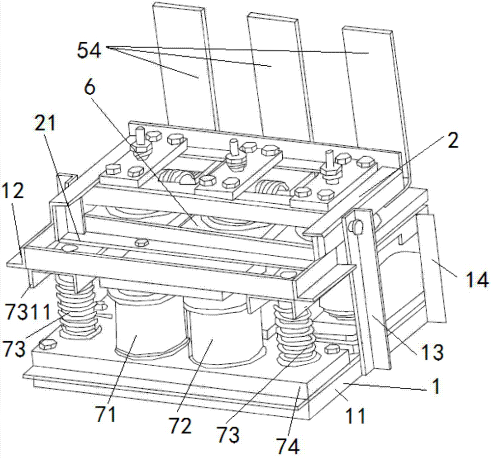
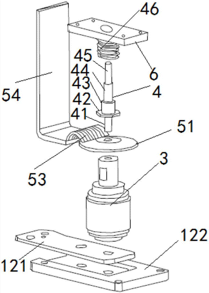
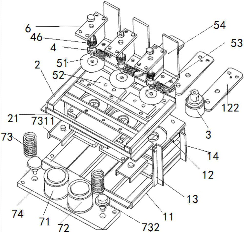
[0028] figure 1 It is a perspective view of an electromagnetic repulsion mechanism built with angle steel in the present invention. figure 2 It is a schematic diagram of the installation of the moving conductive rod and various components of the electromagnetic repulsion mechanism built with angle steel in the present invention. image 3 It is an exploded diagram of an electromagnetic repulsion mechanism built with angle steel of the present invention. Figure 4 It is a cross-sectional view of a permanent magnet mechanism of an electromagnetic repulsion mechanism constructed of angle steel in the present invention.

[0029] See Figure 1 to Figure 4 As shown, in a preferred embodiment, an electromagnetic repulsion mechanism built with angle steel, including:

[0030] Angle steel frame 1, th...


PUM


Abstract

The invention discloses an electromagnetic repulsion mechanism built through angle steel. The electromagnetic repulsion mechanism is characterized in that a permanent magnet mechanism is arranged at the left side of an angle steel frame; a plurality of vacuum contacts are arranged at the right side of the angle steel frame; a rotating angle steel mechanism is arranged at the upper end of the anglesteel frame; a movable iron plate is arranged at the left side of the rotating angle steel mechanism; the permanent magnet mechanism is arranged at the lower part of the movable iron plate; a plurality of movable conducting rods are arranged at the right side of the rotating angle steel mechanism; the lower end of each movable conducting rod is opposite to one vacuum contact; a plurality of repulsion mechanisms are arranged on the angle steel frame; and each repulsion mechanism is located between the plurality of movable conducting rods and the plurality of vacuum contacts. An original repulsion mechanism is improved, so that repulsion coil epoxy boards of the repulsion mechanism are uniform in stress, springback when the movable conducting rods and the vacuum contacts are opened and closed is avoided and the influence on the life of the vacuum contacts is reduced; and meanwhile, the electromagnetic repulsion mechanism has the characteristics of being high in strength, good in reliability and beneficial to assembly.

Description

technical field [0001] The invention relates to the technical field of high-speed switches, in particular to the technical field of an electromagnetic repulsion mechanism built with angle steel. Background technique [0002] The principle of high-speed switching is to use eddy current fields to quickly convert capacitive energy into kinetic energy of moving parts. In order to ensure the fast action of the repulsive force mechanism, the electromagnetic repulsive force has reached the order of tens of kN in hundreds of μs after the capacitor is discharged. When this technology is applied to the AC switch, since the AC circuit breaker is three-phase, there may be excessive instantaneous force during the movement, which will seriously affect the stability of the mechanism. Specifically, most of the current moving parts are a whole transmission part connected by transmission rods of three repulsion mechanisms, and three electromagnetic repulsion forces are generated by the disch...

Claims


Application Information

Patent Timeline
Patent Type & Authority Applications(China)
IPC IPC(8): H01H33/662H01H33/664H01H33/666
CPCH01H33/66207H01H33/664H01H33/666
Inventor 施源郭元超杨建波李福生曹碧颖胡晓羽
Owner SHANGHAI ELECTRICGROUP CORP
Why Eureka
Try Eureka