
Conveying line

A technology of conveying line and conveying frame, applied in the field of conveying line, can solve problems such as low adjustment efficiency, and achieve the effect of high adjustment efficiency and wide application range

Pending Publication Date: 2018-05-04
ZHEJIANG QIANJIANG ROBOT CO LTD
View PDF1 Cites 6 Cited by
  • Summary
  • Abstract
  • Description
  • Claims
  • Application Information

AI Technical Summary

Problems solved by technology

When adjusting the conveying line of this type of structure, it is necessary to adjust the adjustment plate by pulling it back and forth according to the size of the product. The size of the conveyor line, but after adjustment, the distance between the two adjusting plate bodies is fixed. When conveying products of different sizes, it is necessary to manually adjust the distance between the two adjusting plate bodies again. Regulatory efficiency is low

Method used


Image

  • Conveying line
  • Conveying line
  • Conveying line

Examples


Embodiment Construction

[0027] The following are specific embodiments of the present invention and in conjunction with the accompanying drawings, the technical solutions of the present invention are further described, but the present invention is not limited to these embodiments.

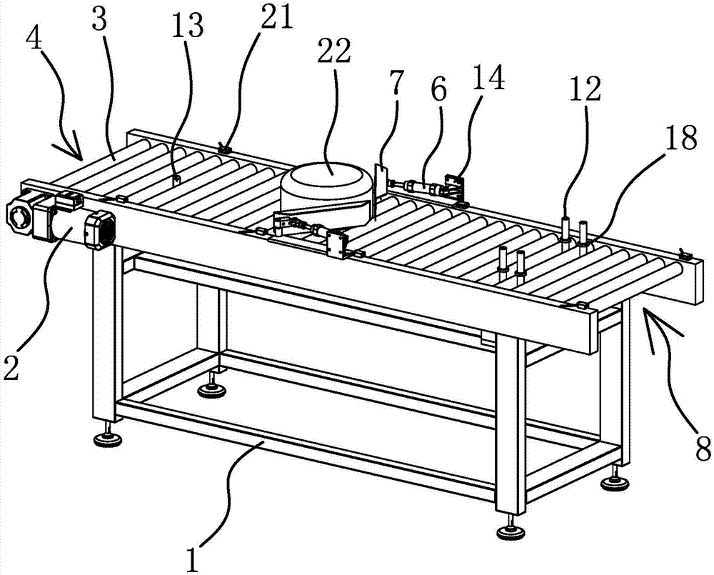
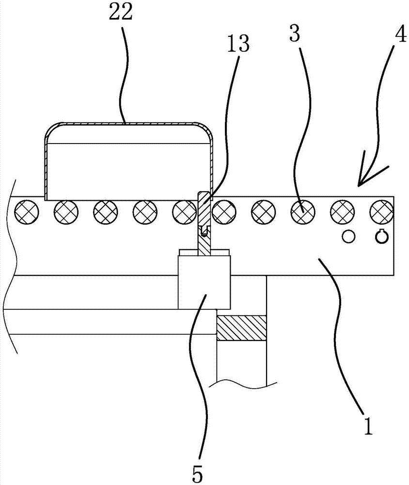
[0028] This conveyor line is suitable for conveying cookware products. This conveyor line is used with the controller and the sensor 21. This conveyor line can automatically sense whether the workpiece 22 has moved to the set position through the sensor 21, and the controller sends a signal to center it. , clamping and positioning the workpiece 22 .

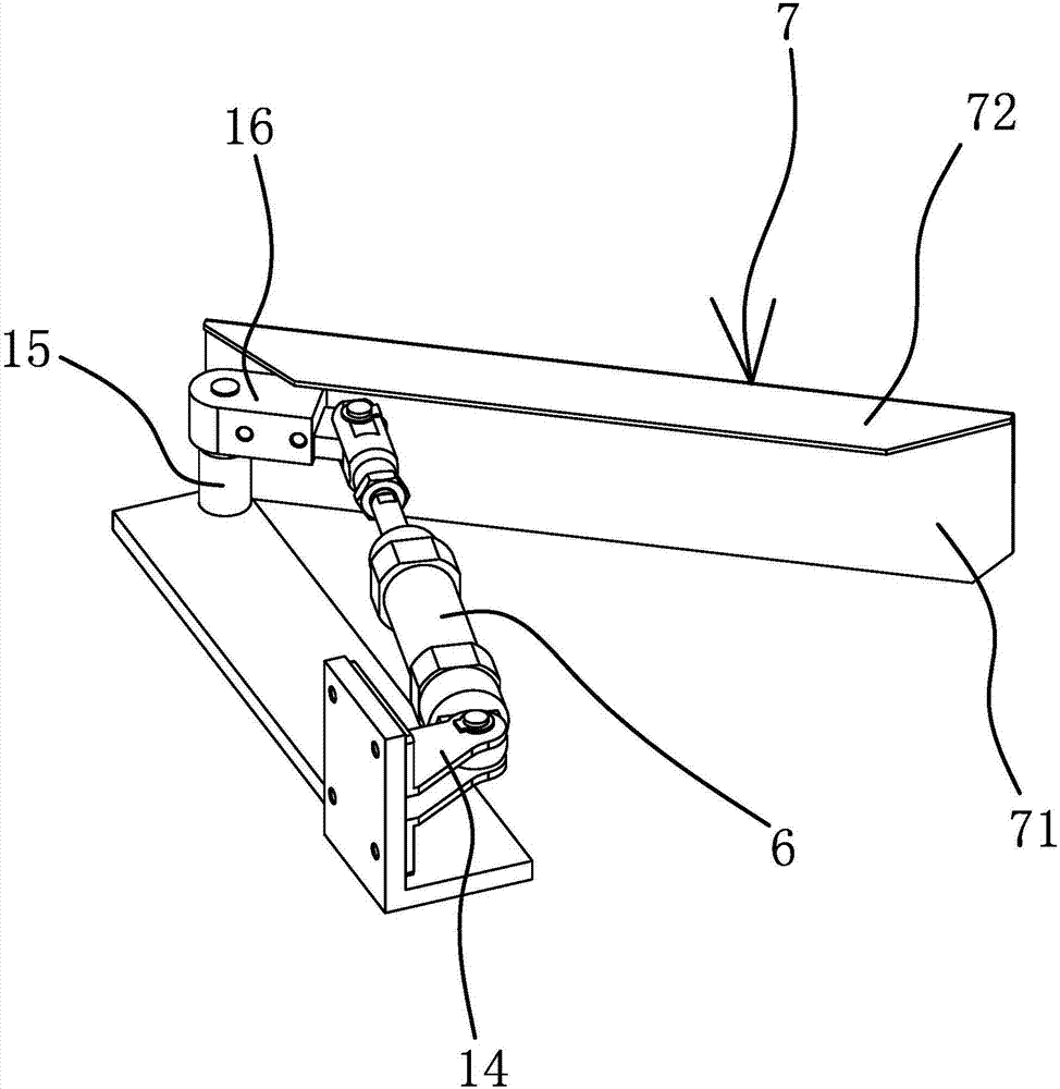
[0029] like figure 1 As shown, the conveying line includes a conveying frame 1, a first driving source 2, a roller 3, a first positioning cylinder 5, a second positioning cylinder 6, a baffle plate 7, a second driving source 9, positive and negative screw rods 10, sliding Block 11, gear bar 12, hinge frame 14, hinge column 15 and mounting frame 19.

[0030] Both the first d...


PUM


Abstract

The invention provides a conveying line and belongs to the technical field of conveying devices. By means of the conveying line, the problems that existing conveying lines are small in application scope and low in adjustment efficiency are solved. The conveying line comprises a conveying rack, a first driving source and multiple rollers. A first locating air cylinder is arranged at a feeding opening of the conveying rack and located below the rollers. The two sides of the middle of the conveying rack are each provided with a second locating air cylinder and a baffle in a hinged manner. The outer end of a piston rod of each second locating air cylinder is hinged to the corresponding baffle. The pair of baffles are symmetrically arranged over the rollers. A second driving source is arrangedat a discharging opening of the conveying rack. A positive and negative tooth screw rod is fixedly connected to an output shaft of the second driving source. A pair of sliding blocks are arranged on the positive and negative tooth screw rod. Multiple stop rods are fixedly connected to each sliding block. Each stop rod penetrates a gap formed between the two corresponding adjacent rollers. The conveying line has the beneficial effects of being wide in application scope and high in adjustment efficiency.

Description

technical field [0001] The invention belongs to the technical field of conveying devices, and relates to a conveying line. Background technique [0002] With the development of the economy and the improvement of living standards, great changes have taken place in people's values. Consumers' hobbies tend to be diversified, and they pursue individuation and specialization, forming various demands, which make enterprises have to provide a variety of products. Products to meet the market, the orders in the factory show a trend of small batches and multiple varieties. In order to cope with this trend, the company introduces manipulators to improve efficiency and flexible production. The conveyor line in the production line also needs to cooperate with manipulators to adapt to flexible and automated production of multiple products. But the tooling on the conveying line that generally adopts at present has poor versatility to products of various specifications. [0003] In respons...

Claims


Application Information

Patent Timeline
IPC IPC(8): B65G21/20
CPCB65G21/2063B65G2207/08
Inventor 胡海洋范理响王璐曹伟强
Owner ZHEJIANG QIANJIANG ROBOT CO LTD
Learn More