
Optical fiber separating jig

A branching and jig technology, applied in the directions of light guides, optics, optical components, etc., can solve problems such as fiber core damage, and achieve the effect of improving work efficiency and simple and labor-saving branching processing.

Inactive Publication Date: 2018-05-04
SUZHOU TABINUO ELECTROMECHANICAL
View PDF4 Cites 0 Cited by
  • Summary
  • Abstract
  • Description
  • Claims
  • Application Information

AI Technical Summary

Problems solved by technology

However, in practical applications, it is found that there are some problems, such as the optical fiber is divided into two strands after passing through the blade, but it is often mixed into one strand after passing through the blade; the blade often causes damage to the fiber core due to its sharp port when splitting

Method used


Image

  • Optical fiber separating jig
  • Optical fiber separating jig
  • Optical fiber separating jig

Examples


Embodiment Construction

[0017] The present invention will now be further described in detail in conjunction with the accompanying drawings and embodiments. These drawings are all simplified schematic diagrams, only illustrating the basic structure of the present invention in a schematic manner, so it only shows the composition related to the present invention.

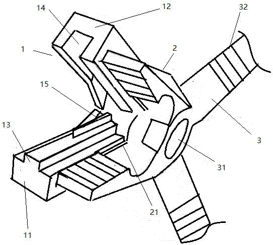
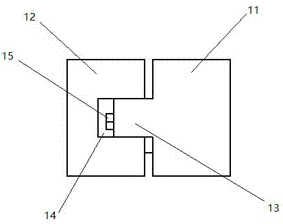
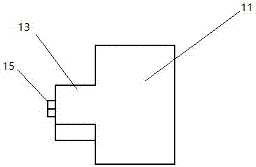
[0018] Such as Figure 1-4 As shown, an optical fiber splitting tool is provided, including a splitting pliers head 1, a wire stripping pliers head 2 and a handle 3, wherein the rear end of the wire stripping pliers head 2 is connected to the pliers handle 3, and the wire stripping pliers head 2 The lower surface and the upper surface of the wire splitter head 1 are affixed together, and the pliers handle 3 controls the opening and closing of the wire stripper head 2 and the wire splitter head 1 through the hinge shaft 31 . The branching pliers head 1 includes a first jaw 11 with an outwardly protruding protrusion 13 and a second jaw 12 with ...


PUM


Abstract

The invention relates to an optical fiber separating jig. The jig comprises a separating tong head, a stripping tong head and a tong handle, wherein the separating tong head comprises a first jaw anda second jaw, the first jaw comprises a bulge bulging outwards and the second jaw comprises a groove denting inwards; the separating tong head comprises a separating component. The jig is characterized in that the back part of the bulge of the first jaw extends downwards obliquely to form a bulge part; the back part of the groove of the second jaw extends downwards obliquely to form a bulge part;the obliquely downward angles of the bulge and the groove are the same; the bulge of the first jaw can be placed in the groove of the second jaw when the separating tong head is closed; the separatingcomponent adopts a structure thickening from front to back. With the adoption of the design, separating treatment can be performed simply and effortlessly and the working efficiency can be improved.Besides, the back parts of the jaws adopt obliquely downward design, so that two separated strands of wires extend in different directions and cannot combine together, and thorough separation is guaranteed.

Description

technical field [0001] The invention relates to a mechanical jig, in particular to an optical fiber branching jig. Background technique [0002] Optical fiber is the abbreviation of optical fiber, which is a light transmission tool achieved by the principle of total reflection of light in fibers made of glass or plastic. Its main function is to transmit information. Optical fiber has the advantages of wide frequency band, low loss, light weight, small attenuation, and no electromagnetic interference. Therefore, it developed very rapidly after its advent. During the use of the optical fiber, not only the protective layer of the optical fiber needs to be stripped, but also the fiber splitting is required, that is, the strand that was originally combined is divided into two strands according to the axial direction. CN205703816U discloses a fixture that integrates the functions of fiber stripping and fiber splitting, and the fiber splitting function is completed by a line spl...

Claims


Application Information

Patent Timeline
IPC IPC(8): G02B6/245
CPCG02B6/245
Inventor 杨保强
Owner SUZHOU TABINUO ELECTROMECHANICAL
Learn More